Welding automation integration succeeds when built on a thorough understanding of your existing production flow rather than on whichever machine promises the highest speed. I have walked into shops where managers started by cataloguing equipment they wanted and only later discovered that their column spacing prevented delivery access or that a positioning table could not sit where the old manual fixture stood. Starting with a detailed audit of your current workflow, material handling constraints, and the weld joints that actually create your bottlenecks changes the integration outcome from a disruptive experiment into a controlled productivity lift. This article addresses the practical steps of retrofitting — from assessment through equipment selection to phased installation — for fabrication managers and project engineers who need greater throughput from lines already in place.
Assessing Your Existing Welding Workflow
Before selecting any equipment, you need a clear picture of what your current line can accommodate and where the real productivity constraints sit. I typically spend two to three days on a shop floor measuring actual cycle times, observing operator movement, and noting which stations consistently accumulate work-in-progress. The goal is to identify the most constrained weld joint or preparation step — often a circumferential seam on a pressure vessel or a long fillet on an H-beam web — and determine whether the constraint stems from weld deposition rate, part handling, fit-up time, or operator fatigue.
Begin by mapping the complete part flow from incoming raw material to final dimensional check. Record the time a component spends in front of a welder versus the time it sits waiting for a crane, a fit-up team, or an inspection sign-off. Many shops uncover that welding automation can only return meaningful gains if the surrounding logistics keep pace, so note which upstream and downstream stations would be affected by a faster welding cycle. If a cutting station already runs at full capacity, doubling the weld speed simply shifts the WIP pile further down the line.
Document physical constraints early: column grid spacing, door widths, overhead crane hook heights, and floor loading limits. A six-metre column boom requires a travel path clear of stored plate and auxiliary equipment, and a three-axis positioner installed on an existing floor must not exceed the slab’s dynamic load rating. I recommend photographing each potential integration point from four angles and bringing those photographs into early discussions with equipment engineers. At ABK, we often superimpose machine envelope drawings onto customer floor plans to identify interference before a single bolt is tightened. If your current shop has an overhead crane rated at 10 tonnes and you plan to position a 5-tonne loaded positioner underneath it, you have already exhausted half the capacity before adding the workpiece — these numbers force choices about workpiece sequence or heavier crane upgrades.
Finally, define the weld process parameters that must be preserved or improved. Write down the material grades, thickness ranges, and the precise joint configurations currently in use. If you are welding S355 H-beam flanges with a submerged arc process, the automation equipment must maintain the same heat input range and travel speed profile. Where your manual welders consistently achieve a 98% first-pass radiographic acceptance rate, set that as the floor for the automated system. The clearer the specification, the less likely you are to discover a misalignment after installation.
Selecting Retrofittable Equipment
Once the process audit identifies the target stations, the next question is which type of automation can be installed with minimal structural alteration to the building and to the product flow. In most existing fabrication shops, a manipulador de soldadura or an adjustable-height welding positioner offers a higher retrofit success rate than a full gantry system because the machine footprint is limited to a rail or a baseplate and does not require a dedicated foundation pit.
A column-and-boom welding manipulator, for example, can be set on existing floor rails if the rail spacing matches one of the standard models. Our LH series manipulators — the LH3040 with 3000 mm horizontal travel or the LH5060 with 5000 mm reach — can often be installed without re-pouring the floor, provided the concrete thickness exceeds 150 mm and the rail fasteners are chemically anchored. This approach lets you automate longitudinal seams on vessels or stiffener-to-web welds on beams without reconfiguring the entire bay.
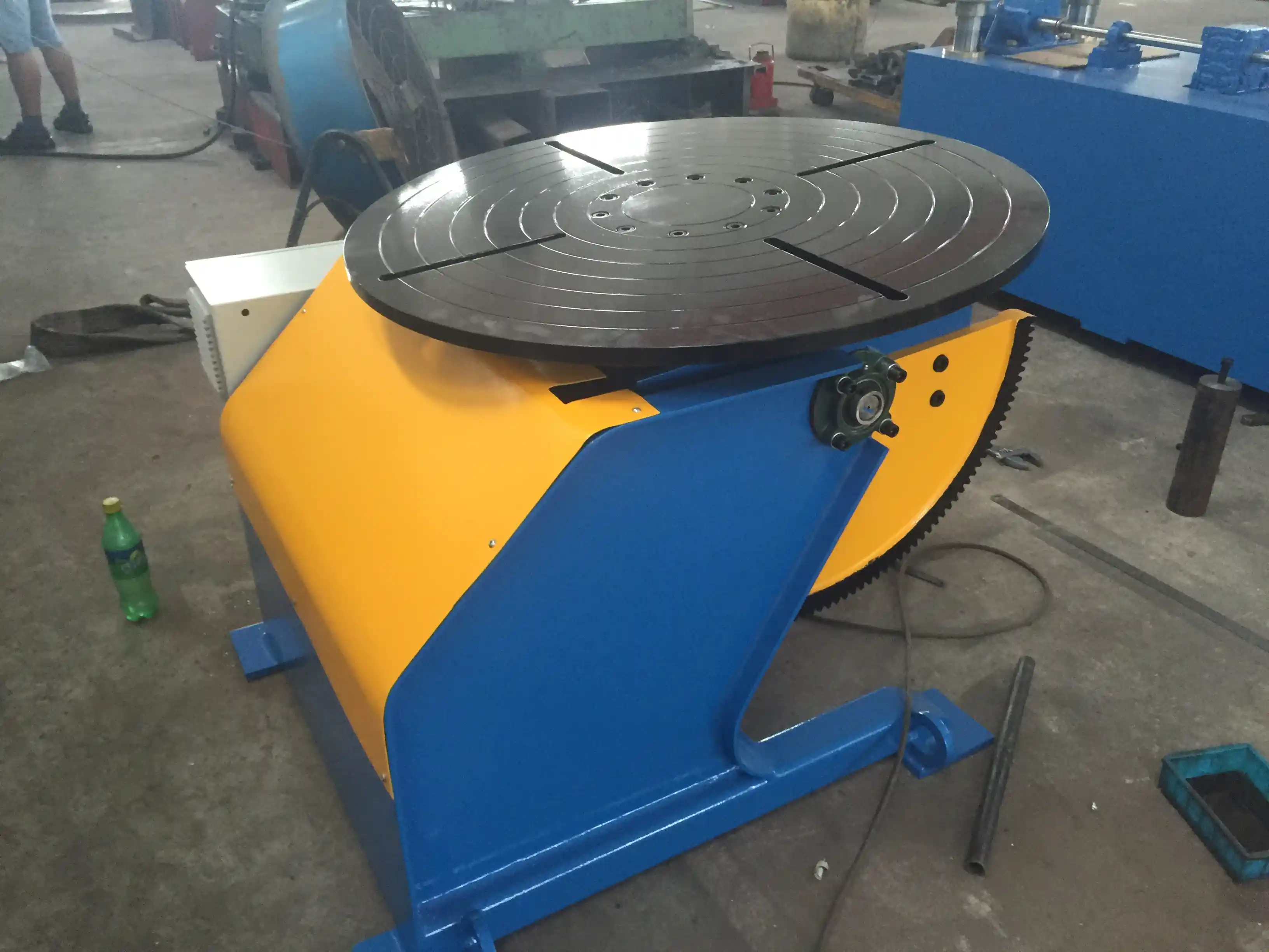
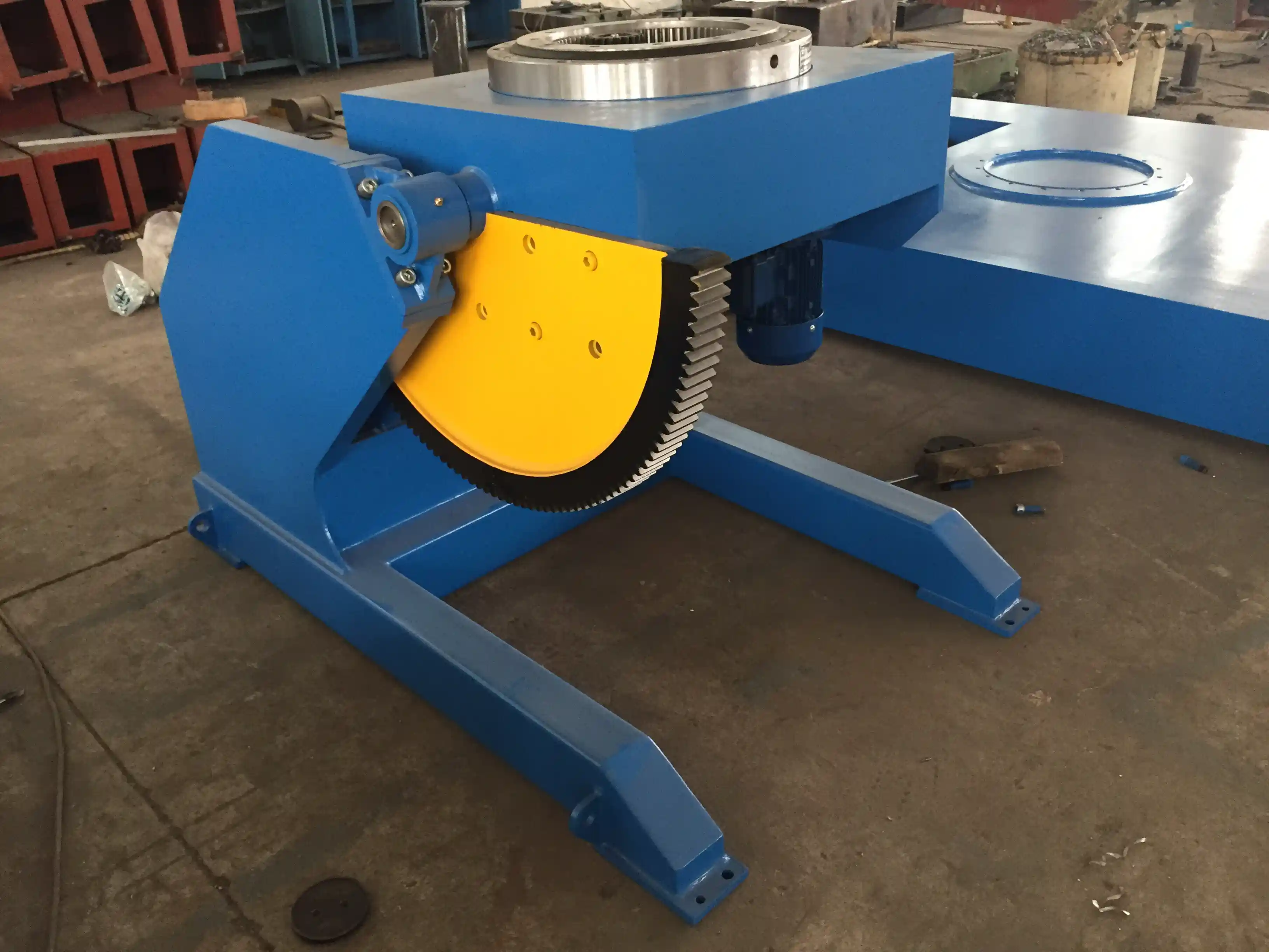
Welding positioners are the other high-impact retrofit candidate. A fixed-height model like the HBJ-20 (2-tonne capacity) or HBJ-50 (5-tonne capacity) only requires a level pad and power connection; the rotation axis brings the weld joint into the flat or horizontal position, enabling a stationary welding head to run at higher deposition rates. For irregularly shaped components, a three-axis positioner such as the 1-ton or 2-ton 3-axis positioner from ABK gives you 360° rotation and 0–90° tilting with ±0.05 mm positioning accuracy, which lets a robotic or mechanized torch access joints that are currently welded out-of-position by hand. In one wind tower flange project, replacing a fixed turntable with a 5-tonne triple-axis positioning table eliminated the need for a skilled fitter to spend 25% of the shift reorienting the flange manually — the machine handled it in the background while the welder loaded the next piece.
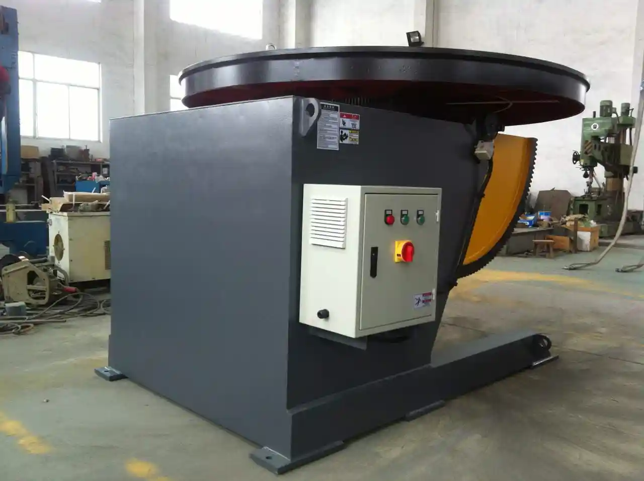
A summary of common positioner models suitable for existing line retrofits illustrates the range:
| Modelo | Capacity | Velocidad de rotación | Rango de inclinación | Typical Retrofitting Footprint |
|---|---|---|---|---|
| HBJ-10 | 1,000 kg | 0.05–0.5 RPM | 0–90° | 1.2 m diameter base |
| HBJ-20 | 2,000 kg | 0.05–0.5 RPM | 0–120° | 1.2 m diameter base |
| HBJ-50 | 5,000 kg | 0.05–0.5 RPM | 0–120° | 1.5 m diameter base |
| LHBJ-30 | 3,000 kg | 0.05–0.5 RPM | 0–120° | L-type, 0.8 m arm |
| 3-Axis 1 T | 1,000 kg | 360° continuous | 0–90° tilt, 180° turn | 1.2 m x 1.5 m floor area |
The selection turns on workpiece weight, required rotation angles, and the available clear radius around the station. In tight bay layouts, I lean toward the 3-axis or L-type positioners because they keep the workpiece centre of gravity low and require less swing clearance than a head-and-tail stock setup.
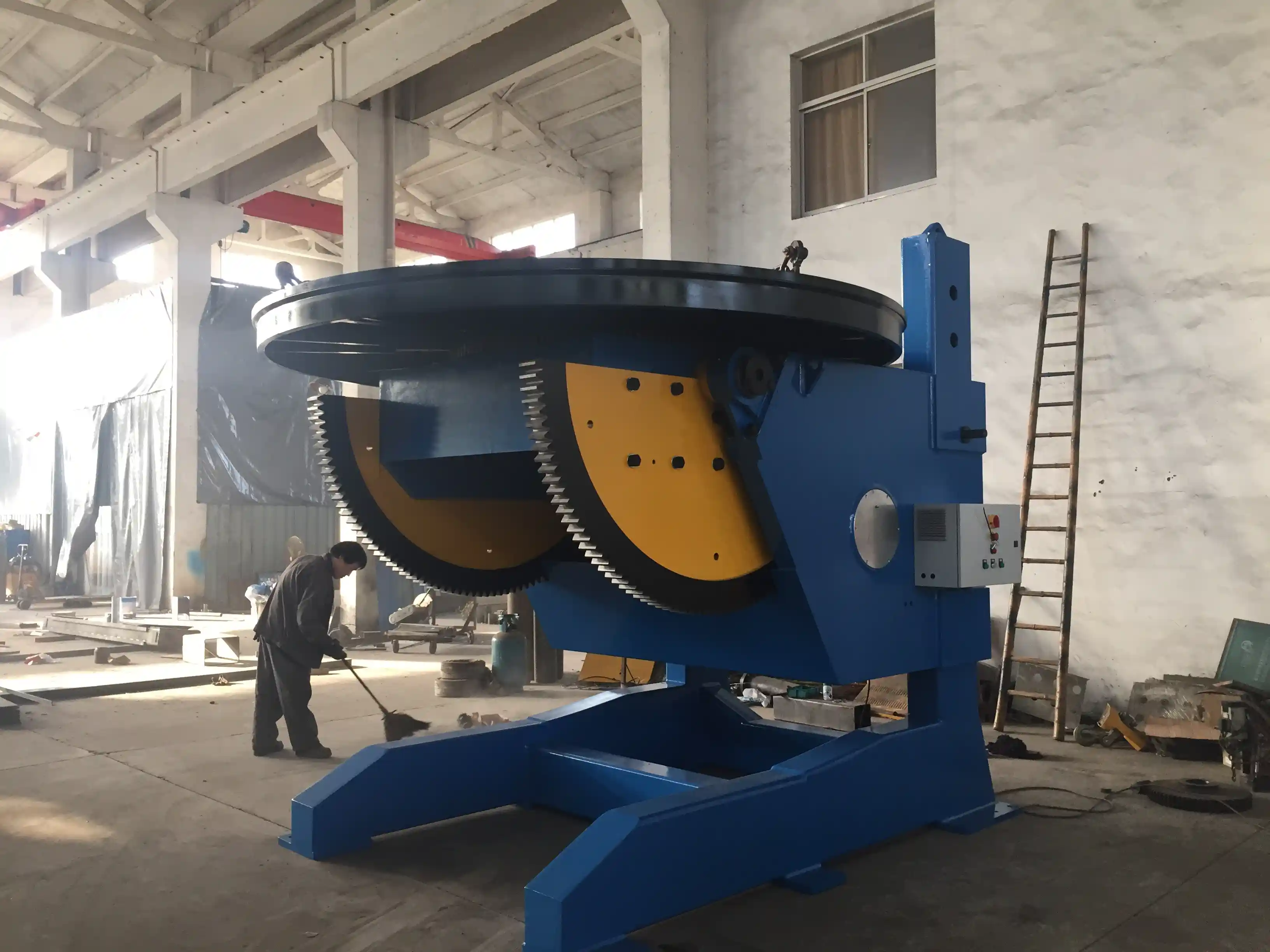
If your program involves heavy cylindrical workpieces — large-diameter pipe girth welds, tank shells, or pressure vessel can sections — a welding rotator set is easier to install than a positioner because the roller frames sit directly on the floor with only electrical connections. Our HGZ-20 or HGZ-40 standard rotators accommodate vessel diameters from 500 mm to 4200 mm and can be repositioned along the bay as the product mix changes. Many shops use a single set of rotators for multiple product families by adjusting the roller spacing and adding idler frames for longer vessels.
Where the existing line includes an overhead crane that cannot easily be rescheduled, consider a welding manipulator with a trolley-mounted column. The trolley moves the entire column along a rail, letting you park the manipulator away from the work zone during heavy lifts. This flexibility often makes the difference between a project that gets internal approval and one that gets delayed by production manager pushback. If you are retrofitting a line that runs 18 hours a day, send your part dimensions and layout drawings to jay@weldc.com — we can model the maximum reach and swing clearance of several manipulator models against your existing column grid before you commit to a site survey.
Optimizing Floor Layout for Automation
The best automation equipment installed in the wrong spot creates a new bottleneck. I have seen a perfectly capable positioner end up covered in cutting dust because it sat directly in the drift path of a plasma table, and a manipulator whose boom collided with an H-beam stack because the storage area had expanded into the arc path after the initial layout was drawn. Integration into an existing floor plan means treating the new equipment as an element that reshapes the entire material flow, not as a plug-in accessory.
Start by simplifying the inbound and outbound path for each automated station. If a workstation currently receives parts from three directions and has no defined staging area, adding a positioner with a fixed rotation footprint will create congestion unless you designate a single feed lane. In a typical bay, I aim for a one-way flow: raw material enters from one side, the automated station sits in the centre, and the welded assembly exits toward the next operation. Even if your building does not permit a straight line, a controlled L-shape flow with a defined turnaround area prevents the ad-hoc forklift movements that scratch finished components and slow down the entire line.
Check the safe arc zone around every automated station. A column-and-boom manipulator with a 5000 mm horizontal reach needs a clear radius of at least that length from the column centre in all welding positions. Mark this on the floor with high-visibility tape and enforce it. In multiple shops, I have found that the primary cause of unplanned downtime after retrofitting is not equipment failure but ancillary equipment parked inside the arc zone because “there was no other place to put it.” If space is tight, a head-and-tail positioner or an HBT-series positioner can reduce the swing radius because the workpiece rotates between two fixed pedestals rather than on a full-diameter turntable.
Power and utilities often become the surprise constraint. A 5-tonne positioner with a 2.2 kW tilt motor and a 1.5 kW rotation motor needs a 380 V three-phase connection within 10 metres of the installation point; longer cable runs require thicker conductors to avoid voltage drop that affects stepless speed regulation. If you are retrofitting a shop built decades ago with limited electrical distribution, adding a sub-panel and a dedicated isolator near the automated station costs a fraction of a full building re-wire and is typically a one-week task. Also verify compressed air availability if the positioner or manipulator includes pneumatic clamping; a regulated 6-bar supply with a 1/2-inch feed line is the minimum I specify.
Minimizing Downtime During Integration
The single greatest source of resistance to retrofitting is the fear of production loss, and I do not dismiss that fear because I have seen shops lose two weeks of output due to poor integration sequencing. The solution is a phased cutover plan where the manual welding station continues to operate while the automated station is built beside it, then a lane switch is executed over a single weekend or a planned maintenance window.
The sequence I recommend: install baseplates and rail systems first without disconnecting any existing utility. Position the machine itself on a Friday afternoon shutdown, align it, and run dry tests with unloaded workpieces. On Saturday, connect power and perform all safety interlock checks. If the machine passes its functional acceptance test, begin welding test coupons and then low-risk production parts while the manual station remains on standby. After a full shift of production-quality output, release the automated station as the primary cell and re-purpose the manual station for low-volume or repair work. This approach keeps the shop’s delivery schedule intact while derisking the equipment changeover.
Several shops we support have adopted a “parallel for a week, then switch” model. For example, when retrofitting a submerged arc welding manipulator onto an existing wind tower section line, the new LH8080 manipulator was installed on a previously unused section of rail. The existing manual submerged arc tractor continued welding all tower cans for the first five days while the operators were trained on the new manipulator’s pendant control and seam-tracking interface. On the sixth day, the manual tractor was shut off, and the manipulator took over 100% of the girth welds. Production volume actually increased that week because the manipulator’s faster travel speed compensated for the slightly lower operator familiarity. If you can arrange a similar short-term overlap — and it almost always costs less than the value of the work-in-progress tied up during a full shutdown — I consider it the single most important integration tactic.
Calculating ROI for Incremental Automation
A retrofit project’s payback does not come only from weld metal deposition rate. The three largest gains I consistently measure are: reduction in rework due to out-of-position defects, elimination of idle time waiting for crane availability, and the ability to run an additional shift with a smaller headcount. If a manual welder spends 35% of the shift rotating a 500 kg assembly and only 65% of the time with an arc lit, a positioner that handles the rotation can push arc-on time above 85%. That shift from 65% to 85% on a single eight-hour station adds roughly 90 productive welding minutes per day — equivalent to an extra half-shift of output per week — without any increase in labor hours.
A 5-tonne positioner like the HBJ-50 typically costs less than the annual fully-loaded wage of one skilled welder in most industrial markets. Even without a robot, pairing that positioner with a mechanized submerged arc or MIG carriage allows a single operator to run two stations concurrently: one welding, one loading. If you add a welding manipulator with a tandem torch arrangement, you can often deposit twice the weld metal per arc-on hour on long straight seams. When calculating ROI, use your actual hourly rework cost, not just the first-pass weld cost. In shops I have audited, the rework rate on manual out-of-position welds runs between 3% and 8% by joint count for vessel girth welds. A positioner that brings the weld into the flat position typically drops that below 1%, which alone can justify the capital expenditure for a line producing hundreds of vessels per year.
I caution against using “total labor savings” as the sole ROI metric because it ignores the fact that the most experienced welders usually move into the role of machine operators and cell supervisors, and their knowledge of heat input, distortion control, and interpass temperature management becomes more valuable, not less. The bottom line improves because output per square metre of floor space rises and the scrap rate falls, not because the payroll shrinks. For shops evaluating a retrofit, the realistic payback window I have observed on a single positioner or manipulator is 10 to 18 months, with larger integrated cells reaching breakeven in 20 to 30 months.
Integration Insight: Retrofitting an H-Beam Line
A few years ago, our team was asked to retrofit an existing H-beam welding line that was producing structural beams for a steel frame building supplier. The line used an older submerged arc tractor on a simple rail, and the web-to-flange fillet welds were being completed in the horizontal position. The shop’s target was to increase throughput by 30% without expanding the building footprint.
After the audit, we identified that the bottleneck was not the welding speed itself but the time required to reposition each beam between the four fillet passes. The crane operator could not keep two stations supplied simultaneously. We installed a 10-tonne welding rotator set — an HGZ-10 with rubber-lined rollers to protect the blasted surface — and added a column-boom welding manipulator (an LH4580 with 4500 mm reach) with twin submerged arc torches. The rotator allowed the beam to be rotated 180° in under 30 seconds without a crane lift, and the twin torches welded both flange fillets simultaneously. The existing rail was extended by 2 metres using bolted-on rail extensions, and the control pendant was positioned at a new operator station with a clear view of both the beam entry and exit. The entire installation took four working days with no lost production because the old tractor continued on the unaffected section of the rail while the new equipment was commissioned.
The result was a throughput increase of 40% — exceeding the initial target — and the manual tractor was retained as a backup for maintenance days. The rework rate on the fillet welds dropped below 1% from a previous 5% due to the manipulator’s consistent travel speed and electrical stickout control. That experience reinforced for me that the most effective retrofits are those where the new automation solves a specific material handling gap rather than simply replacing a welding arc. If your own line suffers from part repositioning delays rather than deposition rate limits, a rotator-plus-manipulator combination is the configuration I would examine first.
Common Questions About Retrofitting Welding Automation
What is the first step to integrating welding automation into an existing line?
The first step is not contacting an equipment supplier but measuring your own process. Spend at least three shifts timing every step of the current workflow and noting exactly which joint preparation or handling operation creates the largest queue of work. Once you know the bottleneck is a 6G pipe weld that takes 22 minutes of manual welding and 14 minutes of crane waiting, the type of automation needed becomes self-evident. Only after you have that data should you start comparing product specifications with your floor constraints.
How do you choose between a positioner and a rotator for an existing line?
Positioners are the better choice when you need to tilt a component to bring a specific joint into the flat position, particularly for irregular shapes like excavator booms or flange-to-pipe assemblies. Rotators, on the other hand, suit cylindrical work where gravity simply keeps the part seated on rollers and the only required motion is rotation. In a shop that produces both pressure vessels and structural frames, I often recommend a small positioner for the assembly work and a rotator set for the vessel girth welds because each handles its own geometry far more efficiently than a single machine forced to do both.
Can I integrate robotic welding with my existing manual line?
Yes, but I suggest starting with a mechanized carriage or a manipulator before adding a robot. A robot requires a positioner with the appropriate interface, a safety cell, and more complex programming. Many shops achieve 80% of the productivity gain by adding a positioner and a submerged arc tractor to an existing manual station, and that simpler configuration can be operating within a week. If your product mix later demands the flexibility of a robot, the same positioner often supports robotic integration via its PLC interface — our 3-axis models are already compatible with ABB, KUKA, and FANUC controllers.
How long does a typical retrofit installation disrupt production?
With parallel installation, the disruption is zero for the majority of the build phase and between 1 and 3 days for the final cutover. I have completed multiple manipulator installations where the machine was assembled and dry-tested on one end of the rail while production continued at the other end, and the switch was made during a scheduled Sunday maintenance window. The key is to have all utilities, baseplates, and safety interlocks verified before the machine occupies its final position. If your shop can allocate a maintenance weekend, a simple positioner can be installed from the forklift-off point to first production weld in 48 hours.
Is it worth automating if my order mix changes frequently?
Automation does not require fixed product lines; it requires well-defined joint types. A positioner that handles a range of workpiece weights from 500 kg to 3000 kg can rotate assemblies of completely different geometries as long as the welding joints fall within the torch reach envelope. The shops that struggle with retrofitting are not those with varied orders but those with poor fixture design. If you can standardize the datum points for each product family so that the weld seam is presented to the torch in a consistent location, even high-mix shops see payback. If your product mix is unpredictable, share your range of part sizes and weights with an application engineer — we frequently design adjustable fixtures that accommodate multiple part families on a single positioner, and you can reach me at jay@weldc.com or +86-13815101750 with your dimensional envelope for a quick assessment.
Welding automation integration into an existing line succeeds or fails based on the quality of the upfront process audit and the discipline of the physical installation plan. If you address the layout, crane coordination, and operator overlap before the machine arrives, you treat automation as a productivity extension of your current operations rather than an isolated project. Our team at Wuxi ABK Machinery routinely helps shops evaluate whether their floors, cranes, and workflows can support specific manipulator, positioner, or rotator models without structural changes, and we coordinate the installation sequence so that your next order ships while the new equipment comes online. Send your floor plan and a description of your target weld joints to jay@weldc.com, or call +86-13815101750, and we will propose a configuration that fits your existing bay and your production targets.
Si te interesa, echa un vistazo a estos artículos relacionados:
¿Espacio de taller demasiado pequeño? Cómo las columnas ahorran espacio 50% a la vez que aumentan la seguridad y la eficiencia
Revolution in Ship Welding: How Welding Positioners Improve Quality and Efficiency
Equipos rotativos de soldadura profesional ABK de Wuxi: solución de soldadura de precisión para la fabricación de recipientes a presión
Problemas de soldadura en torres eólicas de nuevo: Cómo los rotadores inteligentes de líneas de crecimiento aumentan la productividad por 50%
 English
  Español
  Français
  Deutsch
  Português
  Русский