Tube-to-tube welding machine selection does not start with the power source or the weld head. It starts with the joint geometry and the range of tube sizes the machine must hold in alignment under arc load. A butt joint on 25 mm tube places different demands on clamping force, torch angle, and travel speed than a saddle joint on 200 mm header pipe. I tell project engineers to lock the joint list and diameter range before comparing voltage, current, or rotation speed. The machine parameters that matter most are the ones that hold the joint fixed while heat and filler are introduced.
Joint Types That Set Tube-to-Tube Welding Machine Parameters
Tube-to-tube welds in boiler, heat exchanger, and process piping work usually fall into one of five profiles: butt, socket, saddle, flange, or miter. Each profile changes the required torch travel path, the tolerance window, and the clamping method. Butt joints demand the tightest axial alignment, because the weld pool crosses the tube wall edge. Socket joints tolerate a wider insertion window but force the machine to control heat differently around the fillet. Saddle joints need coordinated rotation and oscillation around the branch contour. Flange joints require the weld head to stay square to a face plane while the tube rotates. Miter joints change the weld prep angle around the circumference.
| Joint type | Size range effect | Fit-up tolerance | Main machine requirement |
|---|---|---|---|
| Butt joint | Diameter changes the rotational speed, not the joint prep | Axial offset under 0.5 mm for full penetration | Precision chuck or collet plus axial stop |
| Socket joint | Branch insertion depth sets the fillet leg | Insertion gap must be repeatable | End stop with radial clamping and low heat input control |
| Saddle joint | Branch-to-header ratio sets oscillation width | Contour mismatch changes with offset | Coordinated rotary table and torch oscillator |
| Flange joint | Face squareness controls the seam | Runout under 0.3 mm before tacking | Face squareness check and fixed torch plane |
| Miter joint | Segment angle changes the weld prep angle | Root gap changes around the circumference | Programmable angle stops and seam tracking |
How Joint Type Changes Fit-Up Tolerance
Fit-up tolerance is not a single machine parameter. It is the output of clamping design and part preparation. I have watched a well-built tube-to-tube machine produce unacceptable welds because the chuck let the tube shift 1 mm axially on a butt joint. The same machine welded socket joints cleanly because the fillet path absorbed that movement. When a buyer asks for one tolerance number, I ask which joint type will run most. A machine specified around the most forgiving joint will pass factory tests and then fail on the first difficult production job.
Why Socket and Saddle Joints Need Different Weld Modes
Socket joints need a fillet mode with defined dwell at the stop point. Saddle joints need the torch to climb and descend around the branch contour, so the machine must coordinate rotation speed and torch oscillation. If the weld head is fixed and only the tube rotates, the saddle intersection will alternate between overfill and underfill. I have seen shops try to correct this with manual arc adjustment. The better fix is to specify seam tracking or a cam profile before the machine is ordered.
Tube Size Ranges That Change Clamping and Welding Setup
Tube diameter and wall thickness affect the machine through workpiece weight, surface speed, and heat sinking. A 19 mm tube requires fast rotational speed and low heat input. A 500 mm pipe needs high torque and slow surface speed, with the torch position adjusted for a constantly changing tangent point. Wall thickness matters just as much as diameter. Thin-wall stainless tubes collapse under heavy clamp force. Thick carbon steel tubes require enough arc energy to wet the root without excessive heat input.
Typical machine requests fall into three bands: 12 mm to 60 mm for instrument and heat exchanger tube, 60 mm to 200 mm for boiler and process piping, and 200 mm to 500 mm for header and manifold work. The band defines whether the machine uses a collet chuck, a three-jaw chuck with hardened inserts, or a roller bed with tailstock.
What Size Ranges Can a Single Machine Cover
One machine rarely covers everything well. A machine with a 200 mm maximum clamping diameter can often run tube from 20 mm to 200 mm, but the useful operating window is smaller when the wall thickness range is wide. For boiler panel and heat exchanger work, I recommend splitting the tube range at about 60 mm. Below that, use a compact chuck and lower-torque spindle. Above that, use heavier rollers or a tailstock to carry the tube mass and keep deflection low.
Tube diameter changes how much contact a roller or chuck can maintain. <Soldaduras perfectas en tubos de gran diámetro con equipos de laminación profesionales> covers why professional rolling equipment keeps roundness and fit-up time under control on large-diameter seams.
Positioner and Roller Parameters for Tube-to-Tube Welding
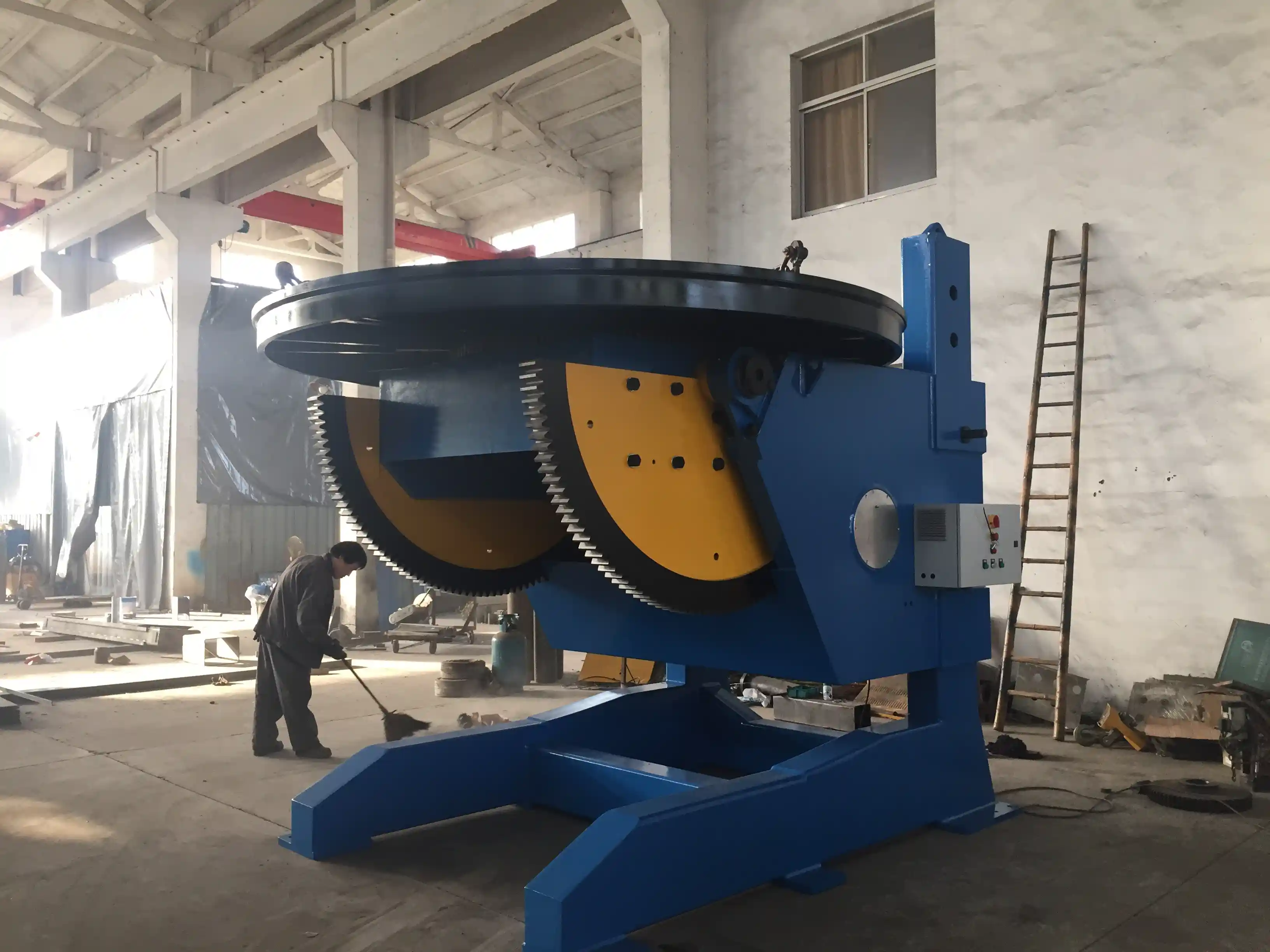
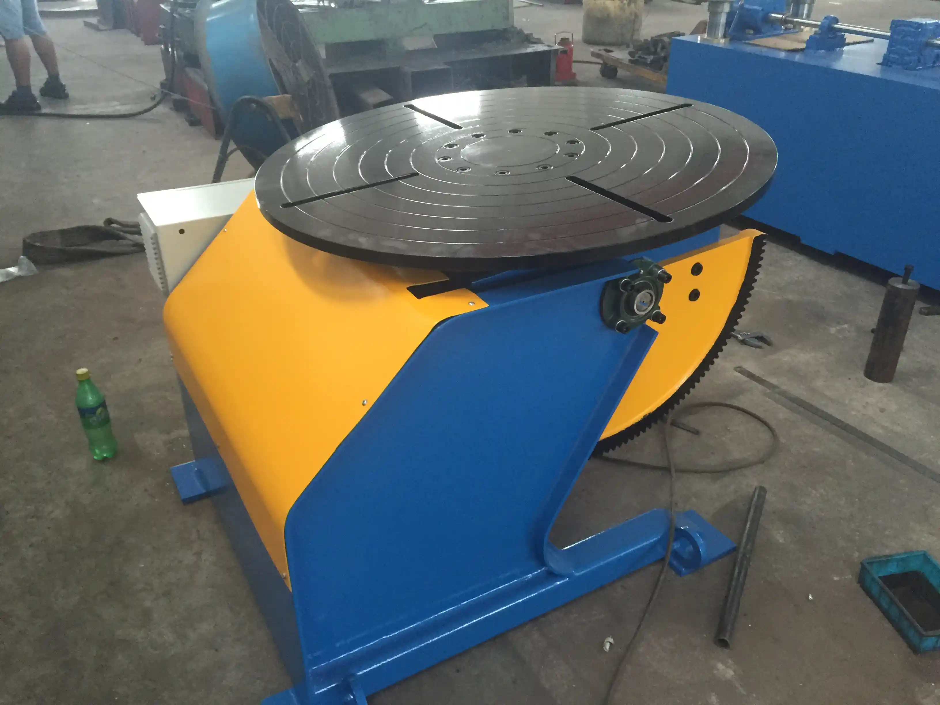
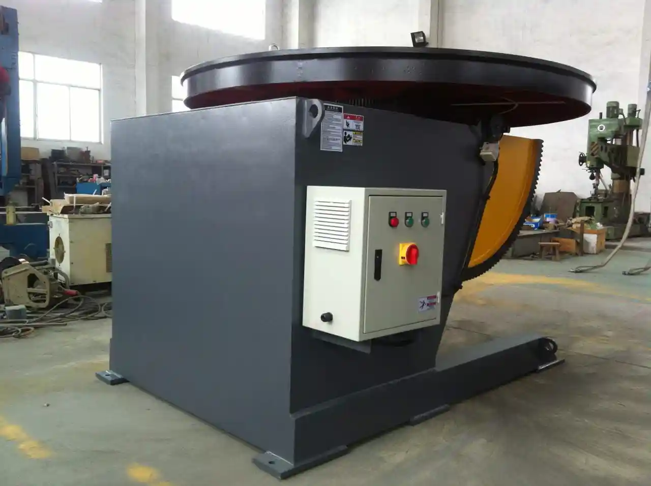
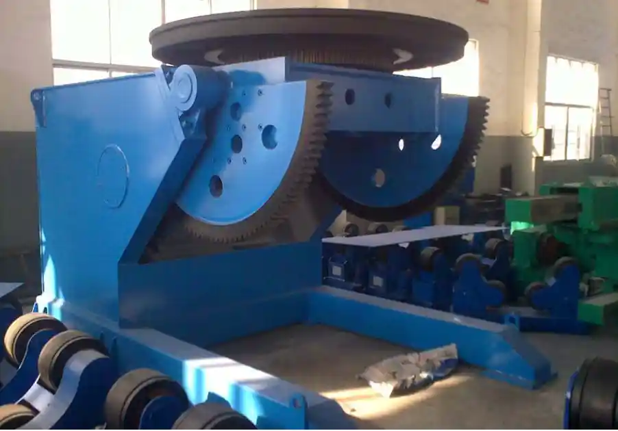
The welding head is only half the machine. The positioner or roller bed holds orientation, rotation speed, and radial position while the torch works. For longitudinal seams on smaller tube, a fixed torch with a rotating chuck is often enough. For circumferential girth seams on longer pipe, the roller speed must match the torch travel speed, and the tube must rotate without axial drift. Positioning accuracy below 0.5 mm is worth specifying when the root gap is tight, because drift at the roller shows up directly as side-wall variation.
Roller drift is one of the first variables to check on girth seams. <Cómo mejorar la calidad de la soldadura de tuberías mediante un posicionador de soldadura de alta precisión> covers how high-precision positioning reduces rework by holding the joint in the same plane through the full rotation.
If your program includes more than one joint type and a diameter range that crosses two fixture sets, the machine specification should be confirmed as a system, not a list of components. Send the tube schedule, joint sketches, and current alignment tolerance to jay@weldc.com before freezing the BOM, and we can check whether one configuration covers the range or whether a second insert set is the lower-cost path.
Common Defect Sources and Inspection Checks
Most tube-to-tube welding defects come from three machine-related sources: alignment shift during rotation, inconsistent clamp pressure, and torch position drift over long runs. Misalignment produces lack of fusion or root concavity on one side only. Clamp pressure variation lets thin-wall tube flare or collapse, changing the gap after tacking. Torch position drift creates a seam that is wide on one side and narrow on the other. I have seen each of these pass visual checks early in a run and then become the full production failure by the third shift.
Misalignment on pipe welds is a pass-rate killer long before it becomes a visible defect. <Pipe Welding Misalignment Issues: How Intelligent Welding Pipe Rotators Boost Oil Pipeline Pass Rates> covers how intelligent pipe rotators correct alignment during rotation and raise the pass rate on pipeline girth welds.
Before release, I record axial drift on the first six welds after setup, clamp pressure at the lowest and highest diameter in each batch, torch standoff after every roll change, and joint gap at four circumferential points. One point or one recording is not enough for a joint that rotates through a moving torch.
Parameter Confirmation Before You Finalize the Machine
Tube-to-tube welding machine parameters are a response to the joint types and size range your line will actually see. Before purchase, confirm the chuck or roller range, the wall thickness capacity at the smallest and largest diameter, the bevel angle and root face settings for the target joint, and the positioner accuracy under full tube weight. If those four points are aligned, the weld parameters will be easier to tune. If they are not, no amount of arc control will recover the lost alignment.
Send your tube diameter range, wall thickness schedule, joint sketches, and monthly welding volume to jay@weldc.com or call +86-13815101750. We can return a parameter table matched to your tube sizes before quotation.
Common Questions About Tube-to-Tube Welding Machine Parameters
What is the first parameter to confirm when buying a tube-to-tube welding machine?
Confirm the joint type together with the full diameter and wall thickness range. Everything else follows from those inputs. A machine can have excellent arc control, but if the chuck cannot hold the tube concentric under load, weld quality will not stay stable. For butt joints, ask for axial repeatability of the clamping system. For saddle joints, ask how torch oscillation synchronizes with rotation. I would not compare power output until the working envelope is defined.
Can one tube-to-tube welding machine cover both small and large diameter tube?
It depends on the range boundary and the wall thickness mix. A machine listed for 20 mm to 200 mm can often handle both ends, but the useful range narrows when tight root gaps are required at both scales. Below roughly 60 mm, a collet chuck gives better concentricity. Above that, roller support or a tailstock prevents the tube from deflecting under arc load. I have found that machines with interchangeable clamp sets are the most practical when the range crosses two size bands, even with higher initial changeover work.
What tolerance should I expect from the machine on a tube-to-tube joint?
The common mistake is expecting the machine alone to hold a perfect joint. The correct expectation is that the machine holds whatever fit-up you create. A good clamping system can hold axial drift under 0.5 mm on a butt joint, but it cannot correct a poorly cut tube end. For flange joints, runout at the table matters more than positioning at the chuck. I have seen shops blame the machine for poor welds when the real problem was bevel variation entering the cell.
How do I decide between a positioner and a roller bed for tube-to-tube welding?
In the projects we support, the decision usually comes down to component length and seam orientation. A positioner is better for short tube assemblies with multiple joint angles, because it gives controlled tilt and rotation. A roller bed is better for long pipe girth seams, because the tube needs continuous support along its length. If the part length is more than about twice the diameter, I lean toward rollers. If the part includes flanges, tees, or multiple branch joints, a positioner is usually the safer choice. Share your joint drawings and current tolerances and we can confirm which configuration fits before you commit.
Si te interesa, echa un vistazo a estos artículos relacionados:
Rotadores y rodillos giratorios: Equipos esenciales para la fabricación moderna de tuberías
Baja eficiencia en la soldadura de conjuntos de tuberías: cómo los soportes de rodillos inteligentes aumentan la productividad en un 501 %
Mejora de la calidad y la eficacia en la fabricación de depósitos y recipientes a presión: El principal valor de aplicación de los posicionadores
Problemas de soldadura en torres eólicas de nuevo: Cómo los rotadores inteligentes de líneas de crecimiento aumentan la productividad por 50%
Desafíos de la soldadura de torres eólicas: Cómo los sistemas avanzados de elevación hidráulica aumentan la producción por 40%
 English
  Español
  Français
  Deutsch
  Português
  Русский