AWS D1.1 welding equipment must deliver precise control over heat input, travel speed, and joint positioning to meet the structural steel bridge code’s demands. After two decades of integrating automated welding lines for heavy fabrication, I can point to a pattern: the difference between passing Charpy V-notch tests and facing costly rework often comes down to the machine’s ability to hold consistent parameters across long weld seams. This article breaks down the specific capabilities manipulador de soldaduras, positioners, and rotator sets need to achieve code‑compliant bridge welds, and how to evaluate those features when selecting machinery.
AWS D1.1 Code Requirements Shape Your Welding Equipment Specifications
Bridge welding under AWS D1.1 introduces constraints that go well beyond the filler metal certification. Preheat and interpass temperature windows, heat‑input ceilings tied to Charpy toughness, groove preparation tolerances, and the acceptance limits for internal discontinuities all push equipment selection away from “any machine will do” thinking. When a butt‑weld in a 50‑mm flange plate must hold a 27‑Joule Charpy value at −29 °C, the heat input cannot wander even 10% from the qualified range.
These requirements translate directly into machine specifications. A welding manipulator must offer speed regulation accurate to ±0.1 m/min and automatic voltage control that compensates for stick‑out changes. A positioner needs angular positioning within ±0.5° so root openings and bevel angles do not drift. Without these controls, an operator’s instinct to adjust travel speed or to reposition the beam manually creates the very variability AWS D1.1 was written to prevent. The code’s Annex B, for example, ties maximum heat input to the toughness category; exceeding it by even a small margin can invalidate the essential variables of the qualified WPS. Machines that enforce the qualified parameters are the quickest path to repeatable results.
Welding Manipulators Deliver the Heat Input Precision Bridges Demand
A column-and-boom manipulator with servo‑driven travel and active voltage control turns the WPS from a document into a locked‑in process. On a bridge girder, the continuous submerged‑arc or flux‑cored runs can stretch 20 meters or more. Manual torch handling over that distance almost guarantees arc‑length drift. I have seen shop trials where a simple switch from manual to manipulator‑based welding cut the scatter in heat input from ±15% to under ±5%, and the ultrasonic test reject rate fell proportionally.
Automatic voltage control is the mechanism that makes this possible. When the contact‑tip‑to‑work distance varies because of beam camber or roller eccentricity, the AVC unit adjusts wire‑feed speed or current to keep the arc characteristic stable. This directly protects the heat‑input envelope written in the WPS. Oscillation, with programmable dwell at the weld toes, ensures complete fusion at the plate edges and reduces undercut—a defect that triggers a repair under AWS D1.1 Table 6.1.
A PLC‑based control system lets the operator store multiple WPS profiles, each with its own travel speed, voltage, oscillation pattern, and stick‑out limit. When moving from a 40‑mm flange‑to‑web fillet to a 60‑mm butt joint, the machine changes parameters with a few touchscreen selections rather than requiring a full recalibration.
| Manipulator Model | Horizontal Stroke (mm) | Vertical Stroke (mm) | Travel Speed (m/min) | Precisión de posicionamiento |
|---|---|---|---|---|
| LH3040 | 3000 | 4000 | 0.12–1.2 | ±0,1 mm/m |
| LH5060 | 5000 | 6000 | 0.12–1.2 | ±0,1 mm/m |
| LH8080 | 8000 | 8000 | 0.12–1.2 | ±0,1 mm/m |
We have supplied manipulators to bridge fabrication lines where the combination of AVC and programmable oscillation eliminated the tendency for slag entrapment at the weld toes, a failure mode that had been driving rework rates above 15%. The stored WPS library meant that a morning shift could weld webs and an afternoon shift could switch to flanges without arc‑time lost to setup.
How automatic voltage control affects AWS D1.1 heat input limits
AVC works by measuring arc voltage and adjusting the wire‑feed motor or power source to restore the set point. This prevents heat input from creeping up when the electrode shortens or from dropping when the gun pulls away. Since heat input is a product of voltage, current, and travel speed, holding two of the three variables constant via automation leaves less room for operator drift. For bridge steels requiring a tight heat‑input range, that closed‑loop control is the only reliable way to stay inside the qualified window.
Oscillation features needed for bridge girder fillet welds
Bridge girder web‑to‑flange fillets often require a specified leg length with a flat or slightly convex profile. An oscillation unit with adjustable width, frequency, and dwell at each sidewall ensures the puddle wets into the corner without undercut. Without oscillation, a single‑pass fillet may lack penetration or leave a concave profile that AWS D1.1 rejects. The manipulator’s ability to repeat the oscillation envelope across a 12‑hour shift is what separates a stable production rate from a constant repair rate.
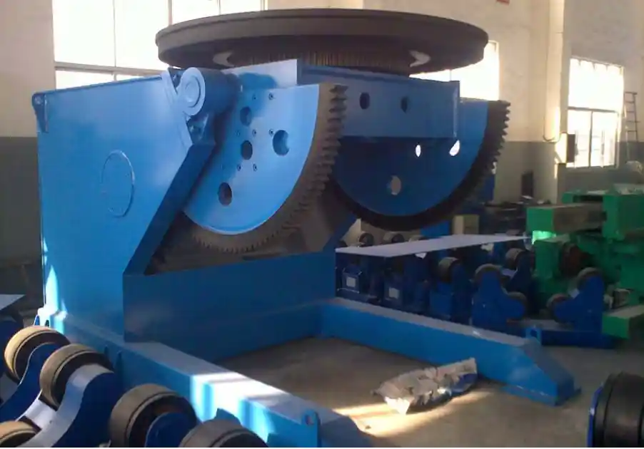
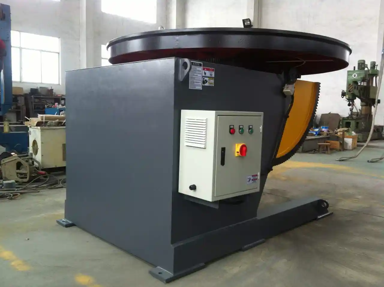
Welding Positioners and Rotators Ensure Groove Alignment Across Long Girders
Girders 30 meters long and 3 meters deep cannot be welded in a single orientation without rotating the assembly. Head‑tail positioners or heavy‑duty rotators turn the beam so every joint can be placed in the flat or horizontal position, which AWS D1.1 generally favors for soundness. The requirement for groove alignment, however, means the rotation must be smooth and indexed accurately.
A positioner with ±0.5° angular accuracy and a mechanical brake that eliminates drift during welding keeps the root opening within the tolerance defined in the WPS. When a beam sags under its own weight as it rotates, an uncontrolled rotator can introduce a millimeter or more of misalignment at the joint. That may not stop the weld, but it changes the bevel geometry enough to cause lack‑of‑fusion defects on the radiographic film.
In a bridge project our team supported, changing from a chain‑driven rotator with manual indexing to a servo‑driven head‑tail positioner reduced the average joint misalignment from 2 mm to below 0.5 mm. The NDT reject rate dropped by almost two‑thirds in the following production lot. The cost of the positioner upgrade was recovered within the first 200 tons of fabricated steel through avoided repairs alone.
Can welding positioners maintain root opening tolerances for groove welds?
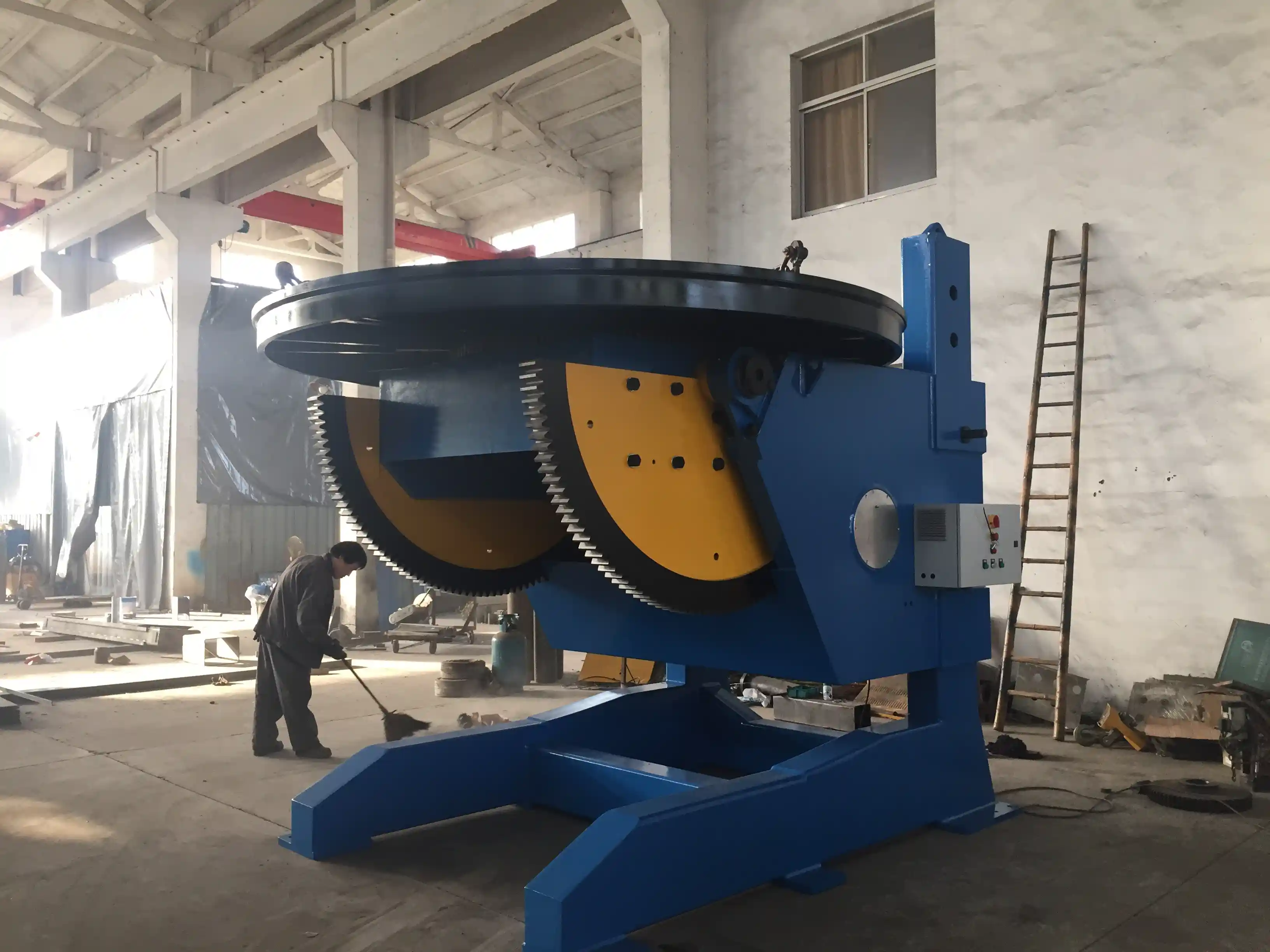
Yes, provided the positioner is sized for the beam’s weight and length. The clamping force, bearing stiffness, and servo‑loop gain must all be sufficient to resist the torque created by an asymmetrical load. For a 15‑ton beam with an offset center of gravity, a standard turntable may oscillate; a purpose‑built L‑type positioner with a long support arm handles the moment without shifting the joint gap.
Rotation accuracy needed for consistent Charpy V-notch results
Toughness testing is sensitive to solidification rate and weld pool geometry. If a positioner rotates unevenly, the weld metal solidifies at varying speeds, creating local regions of coarser grain structure that can fail Charpy tests. A rotation accuracy of ±0.5° combined with speed steadiness under 1% variation keeps the thermal cycle uniform and supports the fine‑grained microstructure required for low‑temperature toughness.
If your bridge project involves full‑penetration groove welds in flange plates thicker than 50 mm, confirming that your positioner’s rotation accuracy aligns with your WPS tolerances is worth doing before finalizing your equipment list. Send your beam dimensions and code requirements to jay@weldc.com, and we can help verify the match.
Selecting the Right AWS D1.1 Welding Machine Involves Capacity and Controls
Matching a machine to a bridge project is not a matter of picking the largest capacity on the datasheet. The three constraints that decide whether the equipment will actually perform are load moment, workspace envelope, and the programmability of the control system.
Load moment is the product of the beam’s weight and the distance from the positioner table center to its center of gravity. A 10‑ton beam with a 2‑meter eccentricity generates a 20‑ton‑meter moment, which a positioner rated only for 10‑ton static load may not handle continuously. The tabletop bearing and worm‑gear drive must be sized for that dynamic condition. Overlooking this is a common mistake; we regularly see fabricators undersize the positioner and then struggle with creeping rotation during welding.
Workspace envelope governs whether the manipulator can reach every joint without repositioning the beam. For a 3‑meter‑deep girder, a manipulator with only 2.5‑meter vertical stroke forces the operator to move the track‑mounted column mid‑weld, a discontinuity that often creates a defect at the restart. A machine’s rated stroke needs to exceed the maximum joint height by at least 500 mm to allow clearance for the welding head and oscillation.
Programmability differentiates a production‑ready machine from a manual assist. A PLC with a touchscreen interface capable of storing 20 or more WPS sets allows the shop to weld multiple joint types in sequence without re‑entering parameters. Integration with seam‑tracking sensors and flux‑recovery systems turns the cell into a closed‑loop production unit rather than a collection of independent components.
Documented Bridge Projects Show Fewer Defects with Integrated Welding Equipment
The evidence from fabrication shops that have moved from manual‑plus‑tack to integrated manipulator‑positioner cells is consistent: NDT repair rates drop, production throughput rises, and the cost of quality falls sharply. In our own experience, shops that pair a servo‑controlled manipulator with a stiff‑bodied positioner report 30–40% fewer ultrasonic rejections because the weld parameters are enforced electronically rather than left to operator judgment.
A typical bridge girder line before automation might run at 60% arc‑on time, with the remaining 40% lost to repositioning, parameter adjustment, and repair grinding. After installing coordinated equipment, arc‑on time moves above 80%, and the throughput of defect‑free weld meters per shift doubles. That gain comes directly from eliminating the pause‑and‑adjust cycle that manual welding introduces.
How automated equipment reduces NDT failure rates in bridge welding
The root causes of most AWS D1.1 NDT failures—lack of fusion, slag inclusion, and incomplete penetration—are tied to process variables that manual welders can control only intermittently. Automated equipment fixes travel speed, voltage, and oscillation pattern, removing the three most common sources of variation. The operator’s role shifts from controlling the arc to monitoring the process, which a PLC‑based interface can assist with trend logging and alarm thresholds. The result is a weld that complies with the WPS not by chance but by design.
Bridge Fabrication Teams Ask These AWS D1.1 Equipment Questions
Is a welding manipulator necessary for bridge girder production?
It depends on two factors: the length of the continuous welds and the toughness requirements. For girders with flange‑to‑web fillets exceeding 10 meters in a single pass, a manipulator is the practical way to maintain the steady travel speed that AWS D1.1 expects. Shops welding shorter stiffener plates manually can still pass inspection, but they accept a higher risk of rework because hand‑held travel speed varies from start to finish.
Can standard welding positioners handle the size and weight of bridge beams?
Standard positioners are available in capacities up to 100 tons, so weight alone is rarely the problem. The challenge is the beam’s geometry. A long, narrow beam applies a high overturning moment that demands a wide base and a stiff support arm. An L‑type or head‑tail positioner designed for long workpieces handles this better than a compact turntable intended for shorter, balanced parts. Verifying the moment rating, not just the tonnage, is the step many first‑time buyers miss.
How does the preheat requirement in AWS D1.1 influence equipment selection?
Preheat alters the arc characteristic because the base metal is hotter and more conductive when the molten puddle forms. The welding machine must compensate for a shallower penetration tendency and a potential drop in arc voltage. Automated control systems can be programmed with separate preheat and non‑preheat parameter sets, switching between them as the interpass temperature climbs. The positioner’s bearings and seals also need to tolerate elevated temperatures without degrading, which is why some shops specify high‑temperature grease and shielded drive components.
What role does flux recovery and seam tracking play in code compliance?
Flux recovery removes spent flux and slag from the weld zone, keeping the arc environment clean and lowering the risk of porosity. Seam tracking adjusts the torch position in real time to follow the joint, compensating for beam camber, fit‑up variation, and thermal distortion. Both functions support the code’s requirements for weld soundness and profile. For fabricators planning an upgrade, confirming that the seam tracker’s correction range matches the typical fit‑up deviation in their shop can prevent a mismatch that leads to off‑center welds. Share your beam tolerances, and we can confirm compatibility with our automation systems.
Making AWS D1.1 Bridge Welding a Reliable Process
Bridge fabrication managers who treat welding equipment as a fixed asset rather than a process‑enforcement tool are the ones dealing with the most rework. When the machine itself becomes the mechanism that holds the WPS parameters, inspection results become predictable. That shift requires positioners with the stiffness to maintain joint fit‑up, manipulators with closed‑loop speed and voltage control, and a control architecture that locks the operator into qualified settings.
WUXI ABK’s line of column‑and‑boom manipulators, head‑tail positioners, and heavy‑duty rotators has been built with these precise controls for structural steel fabrication. The LH‑series manipulators deliver stepless speed regulation and automatic voltage compensation on bridge beam welds up to 8 meters in reach. Positioners ranging from 5‑ton L‑type units to 100‑ton adjustable‑height models provide the load‑moment capacity and angular accuracy that full‑penetration groove welds demand.
For an in‑depth review of your bridge project’s equipment needs, contact Zhang Jian at jay@weldc.com or call +86‑510‑83555592. Send your beam dimensions, joint details, and target code requirements, and we will recommend a configuration that aligns your welding procedures with production‑ready machinery.
Si te interesa, echa un vistazo a estos artículos relacionados:
Cómo mejorar la calidad de la soldadura de tuberías mediante un posicionador de soldadura de alta precisión
Solución revolucionaria para la soldadura de recipientes a presión: Análisis técnico de los posicionadores de soldadura giratorios de 360 grados
Dominar la fabricación pesada: Cómo los soportes de rodillos trepantes se convierten en la piedra angular de la soldadura eficiente
Tired of Complex Welding Challenges? How a 3-Axis Positioner Can Boost Productivity by 70%
Equipos rotativos de soldadura profesional ABK de Wuxi: solución de soldadura de precisión para la fabricación de recipientes a presión