
Wind tower fabrication is a dimensional control challenge before it is a welding challenge. A tower is built from cylindrical or conical sections that must move from plate cutting and rolling through longitudinal seam welding, flange fit-up, girth welding, and final inspection. Every stage depends on how accurately the workpiece is supported, rotated, and positioned.
Small errors in ovality, high-low joint alignment, or root gap become large sources of rework when sections are 3 meters or more in diameter and weigh tens of tons. The right production equipment does more than carry the weight; it keeps the weld joint stable and accessible so the operator can hold the correct travel speed, arc position, and parameter window.
[
The Fabrication Challenges That Shape Equipment Selection
Wind tower production differs from general pressure vessel or pipe welding because the sections are large, the weld lengths are long, and the flange-to-shell connection carries both static and fatigue loads. Four factors usually drive equipment decisions.
First, section roundness determines fit-up. If a rolled shell has local flat spots or diameter variation, the longitudinal seam closure and later girth joints will not align without force. Second, high-low misalignment at the longitudinal or girth seam creates stress risers that are difficult to correct after welding. Third, weld position changes with the joint: longitudinal seams can be welded in the flat or horizontal position with a manipulator and rotator, while flange and section girth welds require controlled rotation or tilting. Fourth, load distribution changes as a section rotates because the center of gravity is rarely at the geometric center.
Standards provide the execution framework. ISO 3834-2 [1] establishes comprehensive quality requirements for fusion welding, while EN 1090-2 [2] addresses the execution of steel structures. IEC 61400-6 [3] is the tower-specific design and verification reference, and AWS D1.1 [4] is commonly used for structural steel weld acceptance in markets where it applies.
Core Equipment for a Wind Tower Production Line
A complete wind tower line usually combines a Windturm-Schweißanlage with workpiece positioners, rotators, and a Schweißmanipulator sized to the section length.
| Production stage | Main equipment | Key selection factors |
|---|---|---|
| Longitudinal seam welding | Column-and-boom manipulator with roller bed | Boom reach, vertical travel, rotation speed match |
| Flange fit-up | Self-centering chuck or fit-up rotator | Diameter range, axial alignment, root gap control |
| Girth welding | High-capacity welding positioner or rotator | Load capacity, rotation speed, anti-creep behavior |
| Internal seam welding | Manipulator with internal boom or special fixture | Reach, wire feeding, flux recovery |
| Final section rotation | Adjustable-height rotator set | Vessel diameter range, hydraulic lift, speed regulation |
For larger sections, equipment selection starts with maximum shell weight and the smallest and largest diameter in the production mix. A rotator that works for a 2-meter diameter can fail to support the roller spacing needed for a 5-meter tower base. The same applies to the manipulator: horizontal travel and vertical travel must cover the full seam without forcing the operator to reposition the column.
Because tower lines are configured around a specific product mix, diameter alone is not enough for a quotation. Send the section diameter range, maximum weldment weight, weld length, and preferred welding position to jay@weldmc.com for a line configuration and cycle-time review.
Girth Welding and the Role of High-Capacity Positioners
Flange-to-shell girth welds are the highest-risk joints in many tower designs. The weld must join a relatively stiff machined flange to a rolled shell, often with a transition in thickness and a tight alignment requirement. If positioner rotation is uneven or the workpiece creeps on the roller bed, the weld pool can move out of the flat position and produce undercut, lack of fusion, or excessive reinforcement.
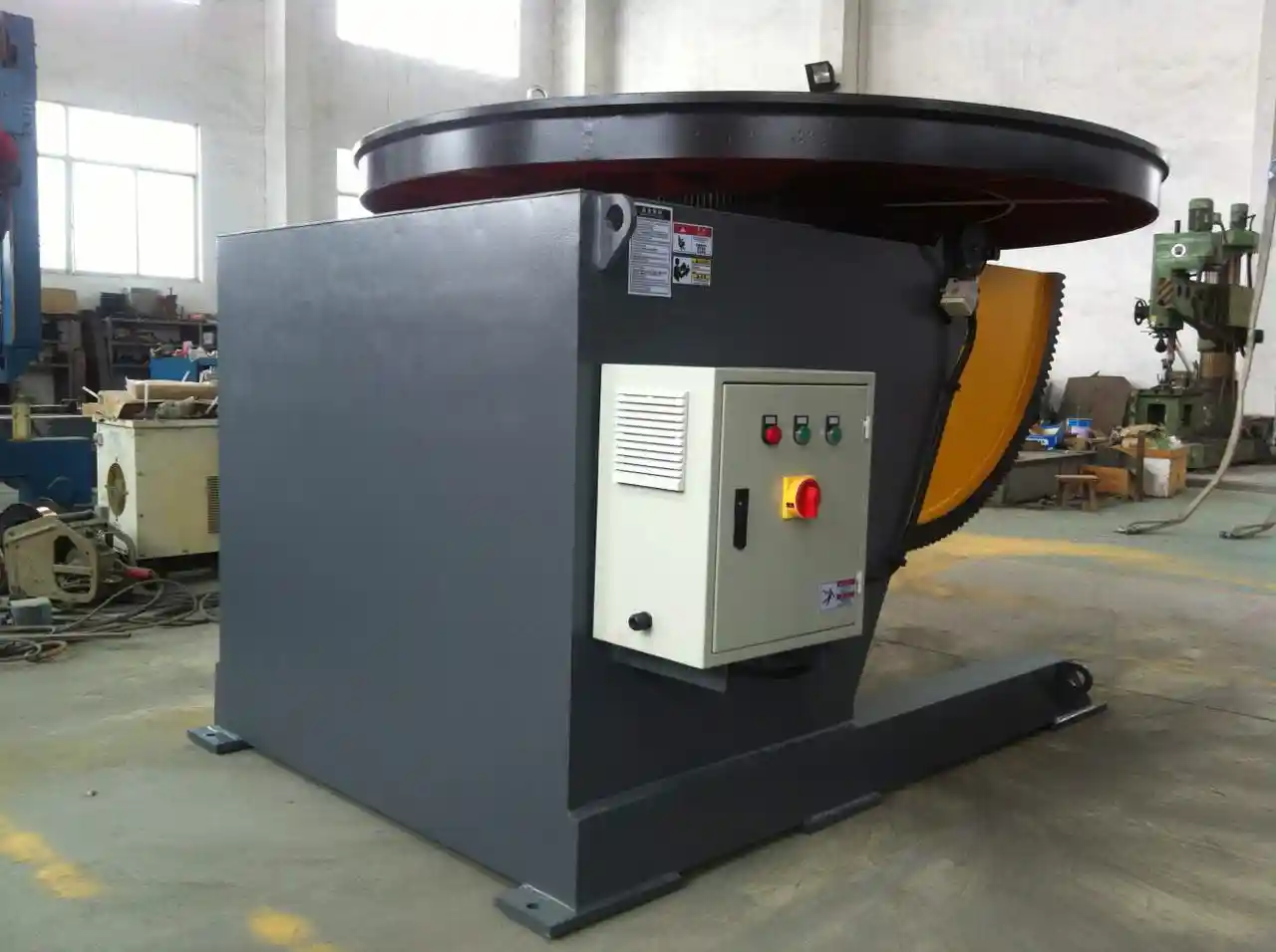
A high-capacity adjustable-height positioner helps by combining rotation with controlled lifting and tilt. For example, a 100-ton adjustable-height positioner may offer a 1,800 mm worktable diameter, 0.05–0.5 RPM rotation speed, 0–135° turnover angle, and an 800 mm lifting range. Those parameters matter less as marketing values than as control limits for keeping a heavy section moving at welding speed without sudden starts or stops.
An adjustable-height design also reduces the handling required between stations. Instead of shimming or re-rolling the section to align the weld plane, the lift system can bring the workpiece to the correct height for the manipulator or column-and-boom setup.
Flange-to-shell girth welds concentrate much of the tolerance and fatigue risk in a tower section. <Verbesserung von Qualität und Effizienz bei der Herstellung von Windkraftanlagen: Die Schlüsselrolle von Positionierern beim Schweißen von Turmsektionen> covers the positioner features that make girth welding predictable.
[
Alignment and Load Distribution During Section Welding
Alignment problems are easier to prevent at the fit-up station than to repair after welding. The fit-up equipment should control the joint gap and high-low condition before the root pass begins. Self-centering chucks and power-clamped roller beds help bring the weld joint into a repeatable position.
For heavy sections, load distribution must account for both static weight and the dynamic forces created during rotation. If the support rollers are too close together or the frame is undersized, the section can sag or creep, changing the joint alignment during welding. Hydraulic lifting and automatic centerline adjustment give the operator a controlled way to correct height and track alignment without manual jacking.
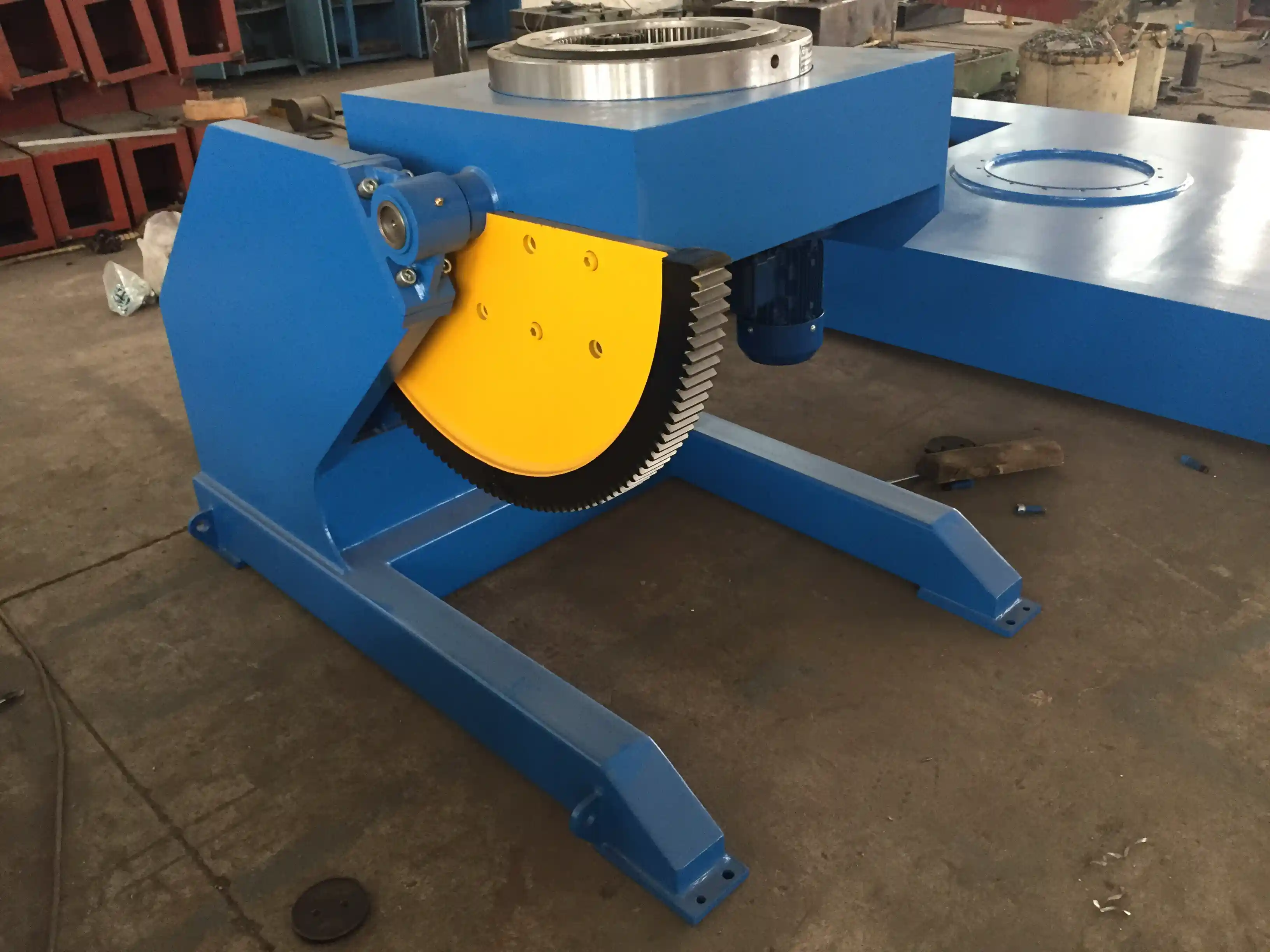
A lifting column welding positioner can combine vertical adjustment with rotation for flange and section joints. The lifting function is especially useful when a line must handle multiple tower diameters, because fixed-height equipment often requires custom stands for each diameter change.
Hydraulic lift and automatic centerline alignment become more valuable as tower sections grow beyond 3 meters in diameter. <Herausforderungen beim Schweißen von Windkraftanlagen: Wie moderne hydraulische Hebesysteme die Produktion steigern von 40%> covers the lift-and-align improvements that matter most in heavy section fit-up.
Automation, Productivity, and Quality Control
Automation in wind tower production does not have to start with a fully robotic line. It often starts with servo-driven positioners, frequency-controlled rotators, and PLC-based weld programs that reduce the variation introduced by operator changes.
A three-axis positioner with synchronized rotation, tilting, and turning can support automated welding cells for smaller tower components such as flanges, door frames, and internal platforms. Positioning accuracy in the ±0.05 mm range with 0.02 mm repeatability is typical of precision three-axis units intended for robotic MIG, TIG, or submerged arc welding. That level of repeatability matters when a robot or tractor follows a pre-programmed path and expects the joint to be in the same place on every part.
For long section seams, the more practical upgrade is closed-loop rotation speed and anti-creep control. If the roller bed speed drifts during a long girth weld, the operator compensates by changing travel speed, which can change heat input and penetration. Better control keeps the rotation speed stable and the weld position constant.
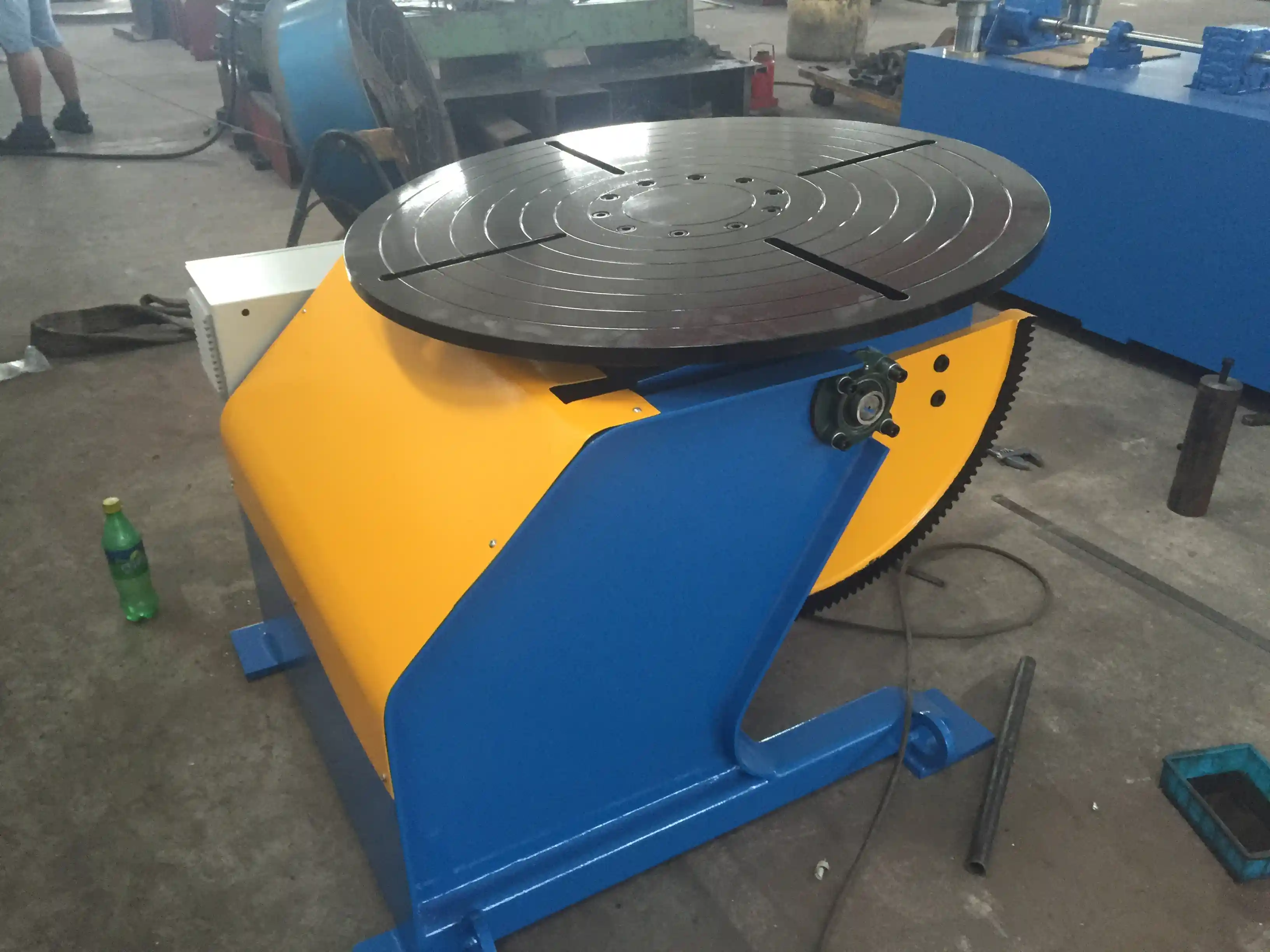
Rotator creep and unstable rotation are common hidden productivity losses in tower fabrication. <Erneut Probleme beim Schweißen von Windkrafttürmen: Wie intelligente Rotatoren für Fertigungslinien die Produktivität steigern – von 50%> covers the control improvements that stabilize rotation during long section girth welds.
[
Request-for-Quote Parameters That Prevent Costly Mismatches
A clear request-for-quote helps avoid equipment that is too light for the heaviest section or too slow for the required cycle time. The following table summarizes the parameters that should be confirmed before purchase.
| RFQ parameter | What to specify | Why it matters |
|---|---|---|
| Vessel diameter range | Minimum and maximum values | Determines roller spacing and idler clearance |
| Maximum weldment weight | Section plus fixture weight | Determines drive torque and frame capacity |
| Weld position | 1G, 1F, 2G, or combination | Determines tilt and manipulator reach |
| Fit-up tolerance | Target high-low and root gap | Determines hydraulic adjustment and encoder feedback |
| Duty cycle | Shifts per day, arc-on time | Determines motor insulation and cooling |
| Control interface | PLC programs, robot compatibility | Determines integration and operator training |
For example, specifying “100-ton load, 0.05–0.5 RPM, 0–135° turnover, adjustable height” is more useful than “large welding positioner.” It tells the manufacturer which frame, slewing bearing, reducer, and drive combination is required, not just the nameplate capacity.
A pre-contract review should also include the fit-up method, crane capacity, and floor height. These constraints often change the equipment layout more than the weld parameters. Send the tower section drawings and station layout to jay@weldmc.com for a technical review before quotation.
[
Project Support and Next Step
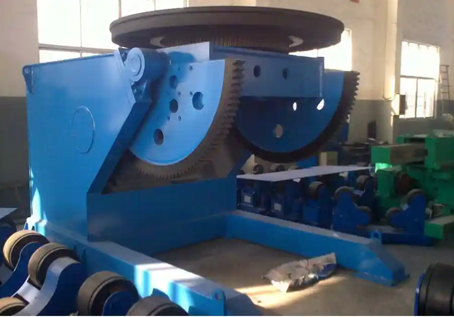
For wind energy projects, production equipment should be evaluated as a complete line rather than a set of isolated machines. WUXI ABK MACHINERY CO., LTD supports wind tower manufacturers with Schweißmanipulators, adjustable-height positioners, pipe rotators, fit-up systems, and complete Windturm-Schweißanlage configurations.
To discuss a new tower line, an upgrade, or a custom station, contact:
- Email: jay@weldmc.com
- Tel: +86-510-83555592
- Mobil: +86-13815101750
Send the section diameter range, maximum weldment weight, and a simple layout plan. The engineering team can recommend the right positioner, rotator, and manipulator combination based on the weld positions and cycle time targets.
Häufig gestellte Fragen
What equipment is needed for a complete wind tower production line?
A typical line includes a welding manipulator, adjustable welding rotators, high-capacity welding positioners, fit-up equipment, and often a self-centering chuck or head-tail positioner for flange and section joints. The exact mix depends on section diameter, weld length, and whether longitudinal and girth welding are done in one station or separate stations.
Which welding positioner capacity is suitable for tower flange welding?
Capacity should be based on the maximum section weight plus fixture weight, not just the shell weight. Many tower flange welding applications use positioners in the 20-ton to 100-ton class, depending on the tower section and whether the positioner supports the shell or only the flange assembly.
How do welding rotators reduce ovality and fit-up problems?
Rotators reduce fit-up problems by supporting the section consistently during rotation and by allowing controlled alignment before welding. Adjustable-height and self-aligning roller designs help bring the joint into position, while anti-creep control prevents the section from moving axially during long seams.
Can wind tower line equipment be customized for different tower diameters?
Yes. Adjustable-height rotators, variable roller spacing, interchangeable worktables, and lifting column positioners are common ways to handle a range of tower diameters. Customization should be based on the smallest and largest diameter in the production plan, not on a single nominal size.
Which standards apply to wind tower welding and structural fabrication?
ISO 3834-2 [1] is commonly used for welding quality requirements, EN 1090-2 [2] for steel structure execution, IEC 61400-6 [3] for tower design requirements, and AWS D1.1 [4] for structural steel weld acceptance in applicable markets.
References
[1] ISO 3834-2:2021, Quality requirements for fusion welding of metallic materials — Part 2: Comprehensive quality requirements.
[2] EN 1090-2:2018, Execution of steel structures and aluminium structures — Part 2: Technical requirements for steel structures.
[3] IEC 61400-6:2020, Wind energy generation systems — Part 6: Tower and foundation design requirements.
[4] AWS D1.1/D1.1M:2020, Structural Welding Code — Steel.
Falls Sie daran interessiert sind, lesen Sie doch diese verwandten Artikel:
Außergewöhnlicher Anwendungsnutzen: Wie Schweißpositionierer mit fester Höhe den Fortschritt in der Offshore- und Schiffbauindustrie vorantreiben (Teil 2)
Die tragende Säule der Schwerindustrie: Die herausragende Leistung von Walzgerüsten in Schlüsselprozessen
Verbesserung von Qualität und Effizienz bei der Herstellung von Tanks und Druckbehältern: Der zentrale Anwendungswert von Positionierern
Wuxi ABK Professionelle Rotationsschweißgeräte: Präzisionsschweißlösung für den Druckbehälterbau
Revolutionäre Lösung für das Schweißen von Druckbehältern: Technische Analyse von 360-Grad-Rotationsschweißpositionierern
 English
 Español
 Français
 Deutsch
 Português
 Русский