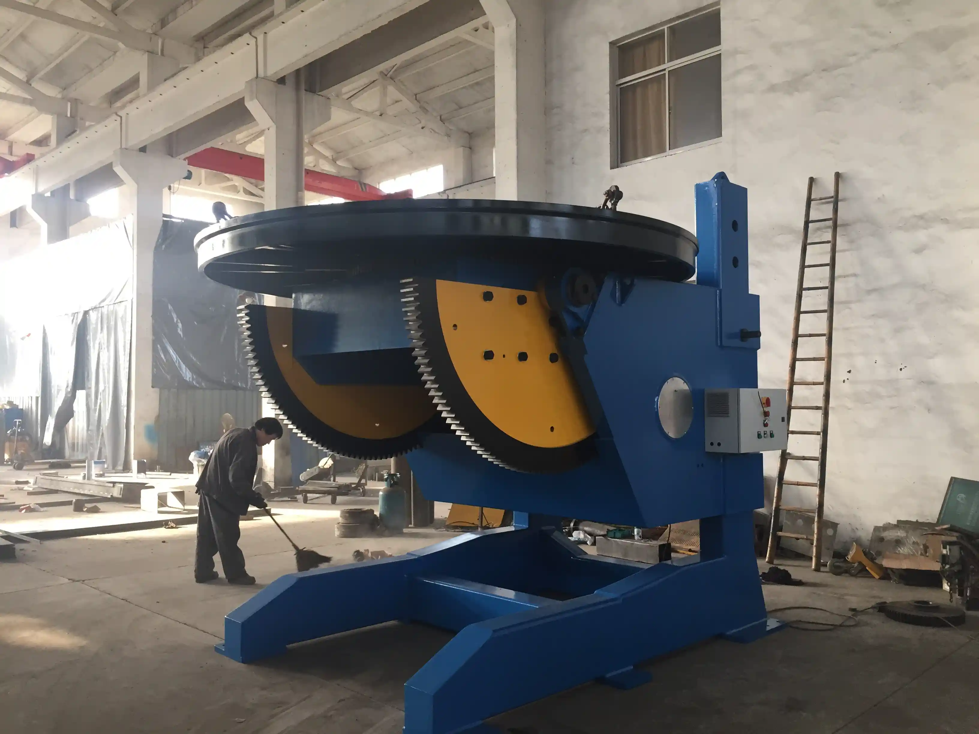
Welding positioners improve weld access and reduce manual repositioning, but only when the safety system is treated as part of the load path. A rotating, tilting table that carries a multi-ton workpiece is a live machine under eccentric load. If the positioner cannot hold a stable orientation, brake reliably, and guard the operator against live movement, production speed becomes a secondary issue. This guide covers the safety features that matter most: load stability, anti-creep control, braking and emergency functions, electrical protection, operator access, inspection, and robotic-cell integration.
Start with Load Stability, Not Just the Safety Label
Many positioner problems begin before the weld arc is struck. The table may be within its rated tonnage, but the workpiece can still create an unsafe condition if the center of gravity is too far from the table face, if the load is eccentric during tilt, or if the part is not clamped against tangential forces.
A welding positioner must be evaluated as a load-handling system, not only as a rotational tool. Key checks include:
- Static load capacity compared with the actual workpiece weight.
- Dynamic load during rotation, tilt, and weld manipulation.
- Maximum eccentric distance and center-of-gravity distance.
- Worktable clamping force, T-slot condition, and fixture stiffness.
- Table height, base rigidity, and floor anchoring.
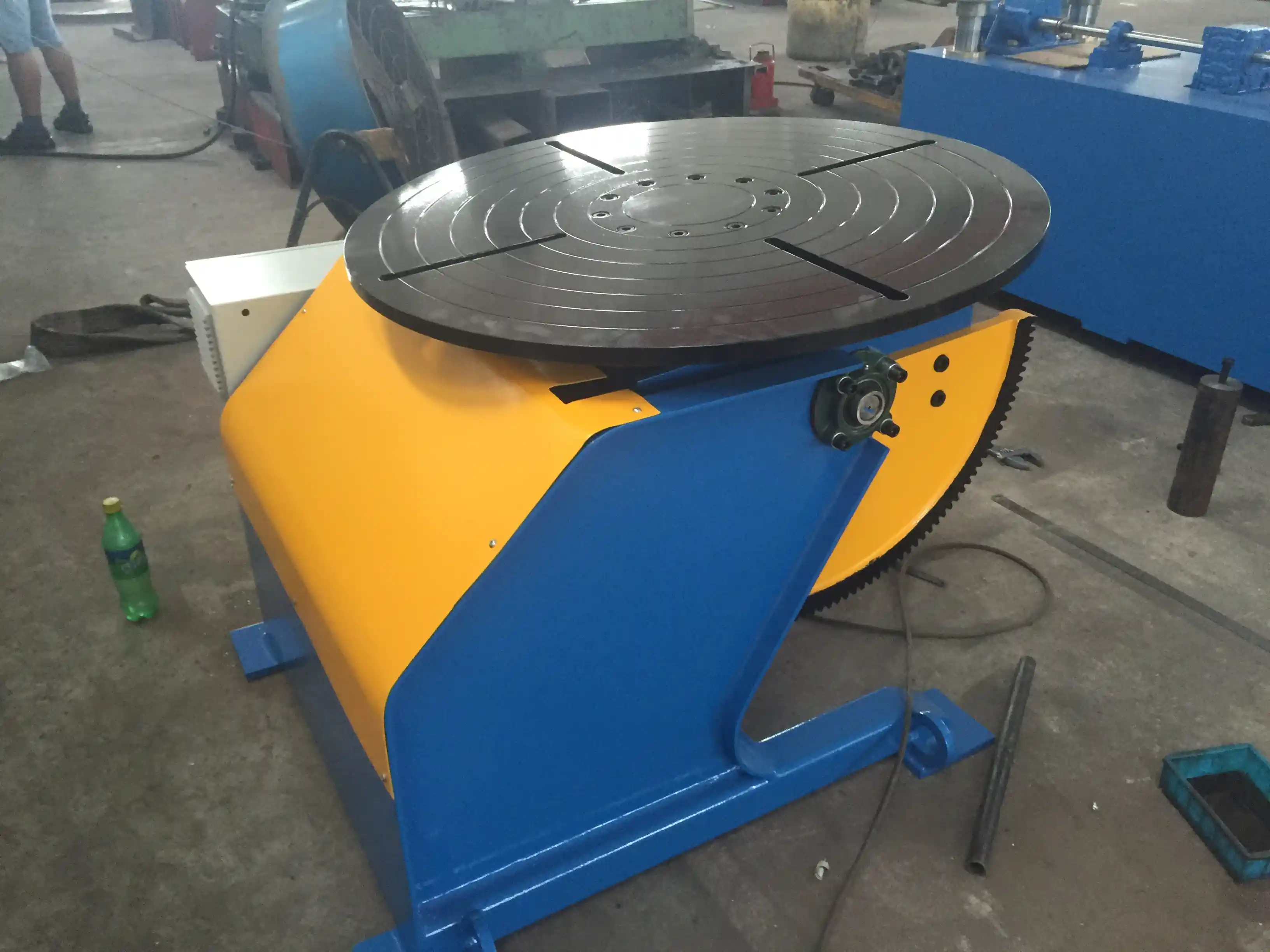
For example, a 1-ton fixed-height positioner may state a maximum eccentric distance of 150 mm and a maximum center-of-gravity distance of 200 mm. If the fixture places a heavy flange outside that envelope, the effective load condition is not the same as a balanced 1-ton part. The result may be excessive bearing wear, uneven rotation, or rollover risk during tilt.
Base construction matters just as much as the drive. Heavy-duty Q235-A steel box-type bases, stress-relieved frames, and precision-machined worktables are product features that help keep the rotating assembly stable under load. Reinforcing the foundation and levelling the machine before use should be part of the installation check, not an afterthought.
Eccentric and live-load movement often appears first as small table creep before it becomes a visible shift. <Kernprobleme und hochpräzise Lösungen für Schweißpositionierer in der Windkraft- und Schiffbauindustrie: Umfassende technische Analyse> covers how wind-power and shipbuilding workpieces with uneven mass are controlled through precise positioning.
Braking, Emergency Stop, and Anti-Creep Protection
A safe positioner must stop on command and hold position until the operator deliberately restarts motion. Emergency stop function should be designed and installed so that pressing the stop device overrides all other motion commands, stops the rotation or tilt axis quickly, and requires a separate reset action before motion can resume. This approach is consistent with machine-safety principles for emergency stop and electrical equipment design [1], [2].
Common stopping and holding features include:
- Brake motors or motor brakes that hold the tilted or rotated table.
- Anti-fall safety pins that prevent uncontrolled table movement during maintenance or setup.
- Overload shutdown that stops the axis when the load exceeds the programmed limit.
- Anti-creep or hold-position control that prevents slow drift under gravity or weld reaction force.
- Emergency stop buttons located at the operator station and at secondary control points.
Anti-creep performance is particularly important on long welds and on vessel seams. If the table drifts during welding, torch-to-joint alignment changes and the operator may attempt to correct the position in the middle of a pass. Some heavy-duty rotator and positioner systems specify anti-creep deviation below 0.5 mm under rated load, but this must be verified on the actual workpiece, not assumed from the specification.
During operator training, the emergency stop should be tested at low speed and with the workpiece clamped. The operator should learn the normal stopping sequence and the difference between an emergency stop and a controlled stop. Repeated misuse of E-stop as a routine pause can mask problems in the drive or control circuit.
Operator Guarding and Access Control
Guarding is not simply a fence around the cell. The positioner work zone should be arranged so that personnel cannot walk under a suspended or tilted load at any point during rotation. When the table tilts a heavy component, the area around the table should be controlled by barriers, floor markings, interlocked gates, or light curtains where automatic operation is used. Guards should be designed and selected according to applicable machinery guarding standards [3].
Welding-specific practices are equally important. Hot work, weld spatter, fume control, and manual torch handling should follow the same operational safety discipline used for welding, cutting, and allied processes [4]. Before starting a positioner cycle, operators should confirm:
- The workpiece is clamped and fixture bolts are tight.
- Loose tools, chocks, chain slings, and cables are outside the travel envelope.
- No person is under the table, inside the tilt path, or on the back side of the load.
- The control pendant is functional, and the operator can reach E-stop without stretching.
- Torch leads, ground connections, and sensor cables cannot be trapped by the rotating table.
Safe access also includes lockout and tagout during fixture changeover, maintenance, and cleaning. Energy isolation is required to prevent unexpected start-up while a worker is inside the cell or on the table. This applies not only to electrical power, but also to stored energy in hydraulic lifting systems, brakes, and suspended axes [5].
Request an Application-Specific Safety Review
If your workpiece exceeds the rated eccentric distance, or if you are adding a positioner to an existing robotic welding cell, the load condition should be reviewed before changing the tooling. WUXI ABK can check table size, tilting capacity, braking performance, and safety interlocks for your part data. Send drawings, part weight, and required weld positions to jay@weldc.com or call +86-13815101750 for a technical review.
Electrical, Control, and Interlock Protection
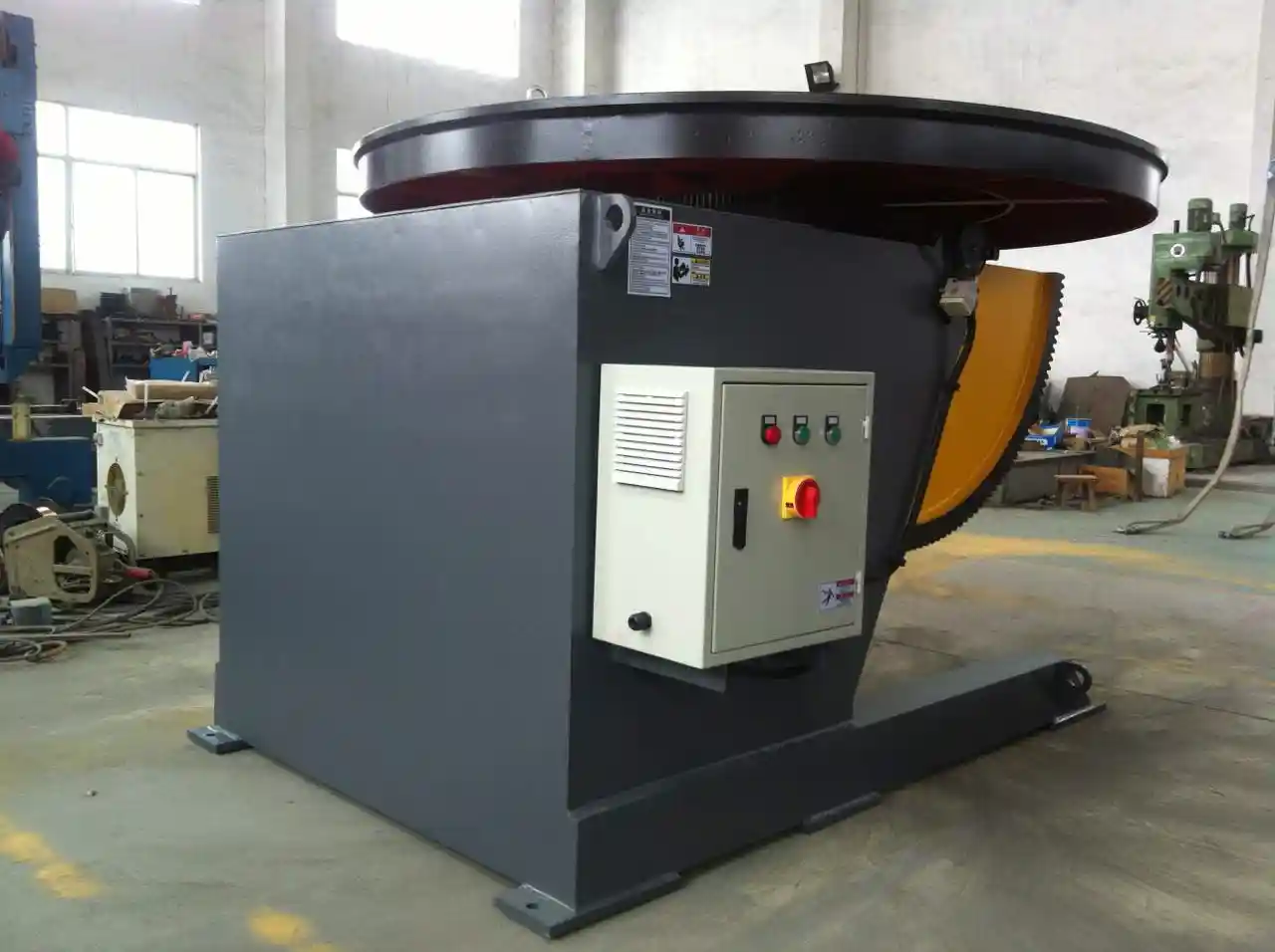
The control system is the link between the operator input and the positioner response. For automated and semi-automatic positioners, the control cabinet should have adequate protection against dust, spatter, and moisture. An IP54-rated enclosure is commonly specified for industrial welding environments. The cabinet should also provide electrical overload protection and proper grounding of the drive, motor, and control components.
Interlock design should be based on the function being controlled. A guard interlock must prevent hazardous motion when a gate is opened, and it should not be possible to bypass the interlock with a simple object. When a positioner is integrated with a robot, the cell controller should manage the positioner as an additional axis. This avoids the dangerous condition where the robot is moving while the operator is trying to adjust the table angle.
Other electrical and control protections include:
- Low-voltage control circuits for pendants and operator interfaces.
- Phase-loss or phase-sequence monitoring where driven equipment is 3-phase.
- Torque monitoring to detect binding, bearing failure, or an unexpectedly high load.
- Emergency stop circuit monitoring and status indication.
- Password or access-level control to prevent unauthorized parameter changes.
A simple weekly check of grounding, cable routing, and cabinet door seals can prevent many intermittent faults. If the operator feels a shock, sees a random motion command, or notices a flickering HMI, the machine should be removed from service until the cause is found.
Installation, Inspection, and Preventive Maintenance
Safety performance degrades when routine maintenance is ignored. The load-bearing and braking components should be inspected daily, monthly, and annually using a fixed checklist. Many positioner failures are not sudden; they begin as slag accumulation, loose bolts, low lubrication, or worn contacts.
| Check | What to verify | Acceptance expectation |
|---|---|---|
| Worktable and fixtures | Clamping, T-slot condition, fixture bolts | No loose or missing fasteners |
| Load limits | Part weight, eccentric distance, center-of-gravity location | Within rated positioner envelope |
| Emergency stop | E-stop activation at low speed | All motion stops and requires reset |
| Brake or anti-fall system | Engage and hold the table | No drift or uncontrolled drop |
| Anti-Kriechfunktion | Table movement under rated load | Within specified deviation limit |
| Grounding and electrical | Ground leads, cabinet seals, contactors | Clean, tight, no discoloration |
| Interlocks and guarding | Open guarded access point | Hazardous motion stops immediately |
| Schmierung | Gears, bearings, slewing ring, actuators | Proper film, no dry or contaminated grease |
| Hydraulic lifting, if used | Hoses, fittings, oil level | No leaks, stable lift |
| Maintenance log | Daily, monthly, annual records | Complete and current |
A safety checklist is most useful when it is tied to the actual workpiece and weld sequence. <Revolutionäre Lösung für das Schweißen von Druckbehältern: Technische Analyse von 360-Grad-Rotationsschweißpositionierern> covers how 360-degree rotating positioners are applied to pressure vessel production with controlled positioning and repetitive weld access.
Daily checks should include removing weld slag from the table and base, checking lubrication points, and inspecting electrical connections. Weekly or monthly checks should include bolt torque, drive mechanism sound, emergency stop testing, and interlock function. Annual maintenance should include worn component replacement, re-lubrication, recalibration, and a full safety-system verification.
Automated and Robotic Cell Safety
When a welding positioner is used with a robot, light curtain, or area scanner, the safety layout must prevent coordinated motion while an operator is inside the protected zone. Robot and positioner integration should follow applicable industrial robot system safety requirements [6]. The positioner should not simply be bolted to the floor and connected to the robot controller; the safety zones, stopping modes, and access paths must be considered together.
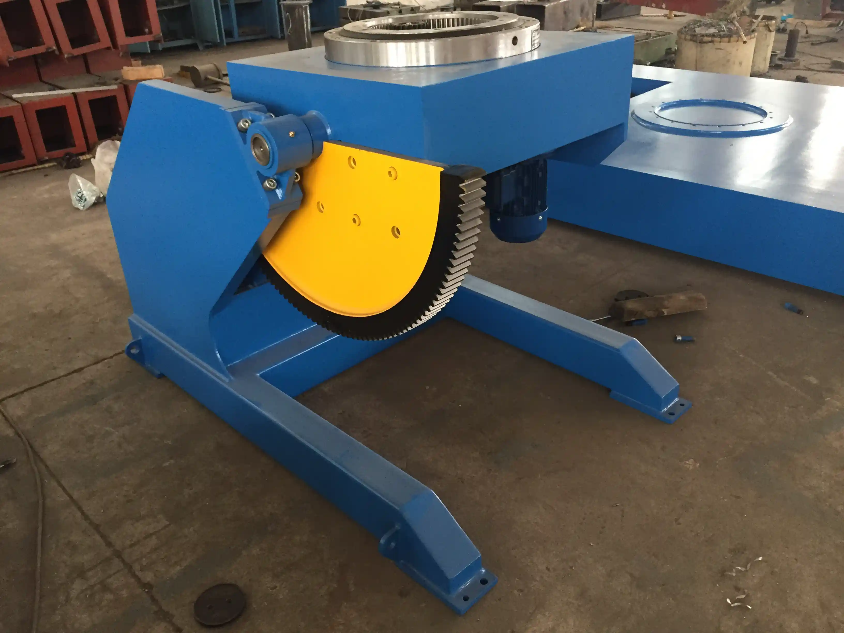
Practical integration checks include:
- The robot cannot move when the cell gate is open.
- The positioner cannot index while a light curtain is interrupted.
- The robot and positioner use a common safe-stop function.
- Manual pendant motion is only available from a defined safe station.
- The operator can see the entire load path without walking behind the positioner.
For wind tower, pressure vessel, and large pipe applications, the positioner may be integrated with a rotator or roller bed. In those systems, axial creep and workpiece separation are additional risks. Roller guides, anti-creep control, and mechanical stops should be included for any long vessel being rotated during welding.
Robotic integration changes the risk profile of a positioner because motion can start without a local operator command. <Schweißmanipulatoren für die Fertigung von Windtürmen: Revolutionierung der Produktionseffizienz> covers how automated positioning and manipulator systems are applied at higher throughput while maintaining control of long workpieces.
Get a Safety-Ready Welding Positioner for Your Application
Do not select a positioner on table diameter and load capacity alone. Work from the full load envelope: part weight, fixture weight, eccentric distance, tilt angle, rotation speed, weld position, and automation interface. A safety-ready positioner should combine a rigid base, verified load capacity, braking and anti-fall functions, overload shutdown, emergency stop, IP-rated controls, and properly designed guarding.
WUXI ABK supplies fixed-height, adjustable-height, L-type, head-and-tail, and 3-axis welding positioners for structural steel, pressure vessel, wind tower, and general fabrication applications. To confirm the correct load rating, tilt range, and safety configuration for your workpiece, contact the application team at jay@weldc.com or call +86-13815101750. For an extended equipment overview, visit the welding turntable solutions page.
Häufig gestellte Fragen
What is the difference between static load capacity and dynamic load capacity?
Static load capacity describes the weight the positioner can hold when the table is stationary and balanced. Dynamic load capacity considers the forces created by rotation, tilt, acceleration, and weld manipulation. A workpiece may be within static capacity but outside the safe dynamic envelope if it is eccentric or if the fixture has a high center of gravity.
What should an operator check before powering the welding positioner?
The operator should confirm that the workpiece is clamped, fixture bolts are tight, the load is within the rated eccentric and center-of-gravity limits, no tools or cables are in the travel path, and the E-stop is reachable. The floor around the table should be clear, and any interlocked guard should be closed before automatic motion is attempted.
How often should emergency stops and safety interlocks be tested?
Emergency stops should be checked according to the manufacturer’s maintenance interval, but a brief low-speed functional test is reasonable before each shift in active production. Guard interlocks and light curtains should be tested weekly, and the results should be recorded in the maintenance log. Any failed interlock must be repaired before the cell returns to service.
Can a positioner be used in a robotic cell without additional guarding?
No. A robotic cell requires an integrated safety design. Gates, light curtains, area scanners, safe-stop circuits, and controlled access points must be considered together with the positioner and robot controller. Adding a positioner changes the robot envelope and introduces additional motion hazards, so the cell safety system must cover both machines.
What does anti-creep protection actually prevent?
Anti-creep protection prevents slow table movement under gravity, weld reaction force, or brake leakage when the positioner is supposed to hold a fixed orientation. Without it, the weld seam can drift during a pass and the operator may need to stop and re-align, which creates both quality and access problems.
References
[1] ISO 13850:2015, Safety of machinery — Emergency stop function — Principles for design. International Organization for Standardization, 2015.
[2] IEC 60204-1:2016, Safety of machinery — Electrical equipment of machines — Part 1: General requirements. International Electrotechnical Commission, 2016.
[3] ISO 14120:2015, Safety of machinery — Guards — General requirements for the design and construction of fixed and movable guards. International Organization for Standardization, 2015.
[4] ANSI Z49.1:2021, Safety in Welding, Cutting, and Allied Processes. American Welding Society, 2021.
[5] ISO 14118:2017, Safety of machinery — Prevention of unexpected start-up. International Organization for Standardization, 2017.
[6] ISO 10218-2:2011, Robots and robotic devices — Safety requirements for industrial robots — Part 2: Robot systems and integration. International Organization for Standardization, 2011.
Falls Sie daran interessiert sind, lesen Sie doch diese verwandten Artikel:
Wuxi ABK Professionelle Rotationsschweißgeräte: Präzisionsschweißlösung für den Druckbehälterbau
Probleme mit Ausrichtungsfehlern beim Schweißen von Rohren: Wie intelligente Schweißrohrrotatoren die Durchlaufraten von Ölpipelines erhöhen
Außergewöhnlicher Anwendungswert: Wie Schweißpositionierer mit fester Höhe den Fortschritt in der Offshore- und Schiffbauindustrie vorantreiben
 English
  Español
  Français
  Deutsch
  Português
  Русский