
Heavy-section fabrication depends on positioning accuracy as much as welding power. A heavy-duty welding positioner rotates and tilts large parts so the weld seam sits at the optimum flat or horizontal position. That single change reduces out-of-position welding, stabilizes melt pool control, and keeps operators or robots working at a consistent travel speed. In large component fabrication — pressure vessels, wind tower sections, bridge girders, excavator booms, or rail bogies — the positioner is not a convenience. It is the workholding structure that determines weld access, repeatability, and cycle time.
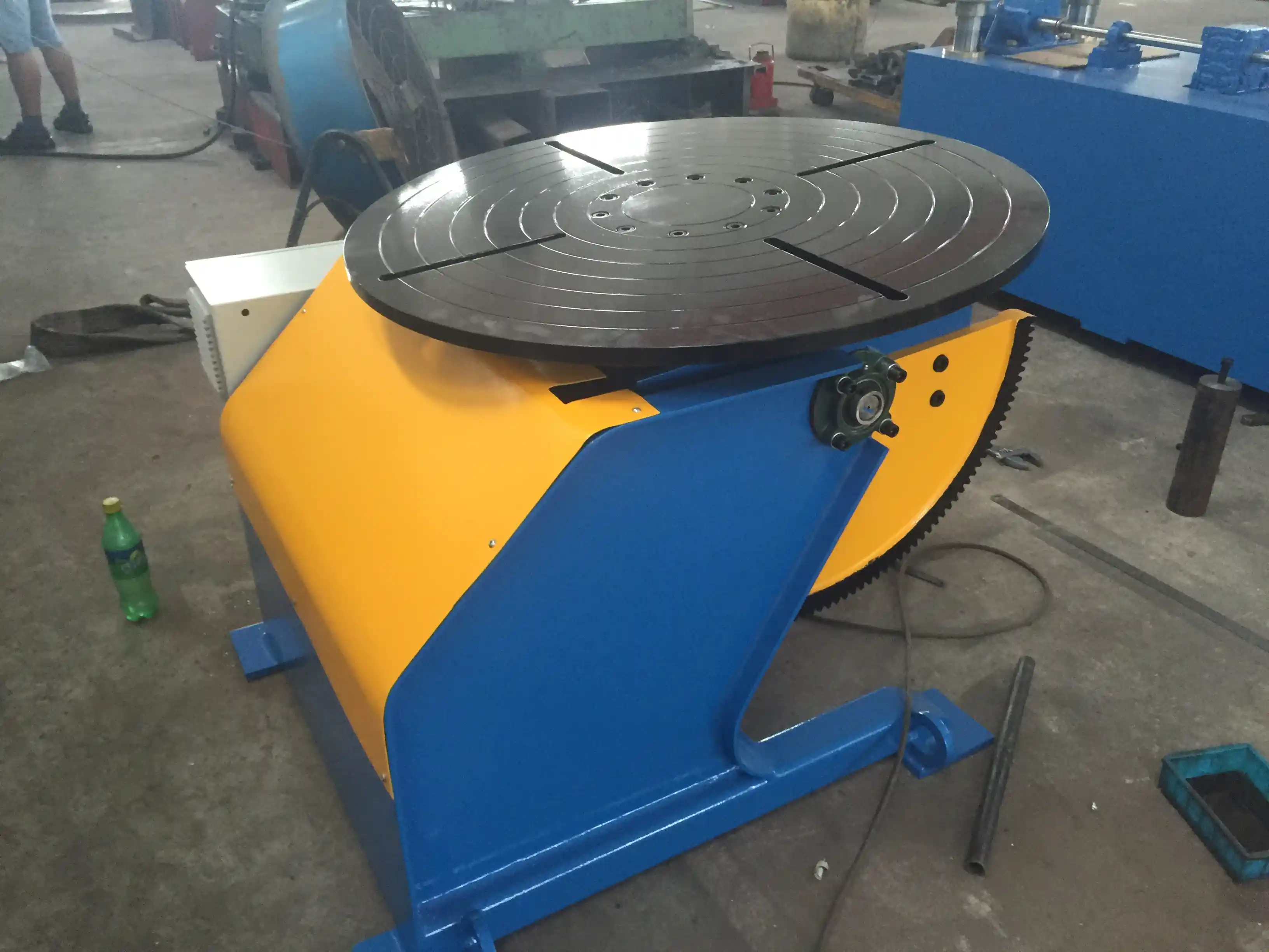
How Heavy-Duty Positioners Improve Large Fabrication
For components above 1 t, manual repositioning is slow and inconsistent. Cranes can turn a workpiece, but they do not provide controlled rotation, angular positioning, or safe tilt. A heavy-duty positioner provides controlled rotation around one or more axes, while tilting sets the weld joint in a process-friendly orientation.
In general fabrication, the largest gains come from:
- Moving the weld seam to the flat or horizontal position.
- Reducing fit-up error by using reference surfaces and controlled rotation.
- Making continuous circumferential welds without stopping to re-rig.
- Supporting robot paths with repeatable orientation.
These gains are not automatic. They depend on matching the positioner’s capacity to the part’s actual center of gravity, not just its total weight. ISO 3834-2 requires welding operations to be supported by suitable work equipment and controlled holding arrangements capable of maintaining alignment and positioning during welding [1]. That requirement is especially relevant for heavy parts because weld distortion and dynamic rotation change the load path.
Load Distribution and Stability: The Core Engineering Problem
The load capacity stamped on a positioner is only part of the selection decision. A heavy component can weigh 5 t but generate far higher effective loading if its center of gravity is not directly over the table center. The relevant value is the eccentric moment — the product of part weight and the distance between the center of gravity and the rotation axis.
Manufacturers typically state both maximum load and maximum center-of-gravity distance. For example, a fixed-height 5 t positioner may permit a 300 mm center-of-gravity offset under controlled conditions. If the same part is mounted at 500 mm, the positioner may be mechanically overloaded even though the part weighs less than rated capacity. The same logic applies to dynamic load during acceleration and deceleration, so the drive train must be sized for peak moment rather than static weight alone.
Rotating a heavy part with an off-center load changes the overturning moment faster than a simple weight calculation suggests. <Kernprobleme und hochpräzise Lösungen für Schweißpositionierer in der Windkraft- und Schiffbauindustrie: Umfassende technische Analyse> covers how eccentric loads affect stability in wind power and shipbuilding applications.
Stability also depends on base rigidity and worktable flatness. A heavy-duty steel box base, stress-relieved before machining, resists distortion from concentrated fixture loads. Worktables with T-slots and conductive slip rings support continuous rotation while maintaining ground and signal continuity for welding current.
For very long or cylindrical parts, a head-and-tail positioner is often more stable than a single table. The tailstock supports the far end, reduces bending moment, and keeps the rotation axis aligned. This is especially important for pipe spools, shafts, and pressure vessel shells.
Selection Factors for Heavy-Duty Positioners
Proper selection starts with the workpiece envelope and the weld map. The positioner must support the part at every orientation required by the welding sequence, not just at the starting position. Key factors include:
- Load capacity and eccentric moment. Confirm both static load and allowable center-of-gravity offset.
- Table diameter and T-slot layout. The table must allow direct clamping without excessive overhang.
- Rotation and tilt range. Complex weldments may need 360° rotation plus 0–135° tilt to reach all seams.
- Speed range and control. Low-speed stability matters for large-diameter circular welds; stepless control supports fine adjustment.
- Height adjustment. Lifting or adjustable-height designs reduce crane involvement and improve operator access.
- Positioniergenauigkeit und Wiederholgenauigkeit. Robotic cells require tighter repeatability than manual welding.
- Integration features. PLC and touchscreen control, robot interfaces, and IP54 protection simplify automation.
The table below shows representative specification ranges from WUXI ABK product documentation for heavy-duty positioning equipment. It is provided as a reference for comparing capacity classes, not as a universal sizing table.
| Equipment class | Load capacity | Table diameter | Tilt / turn range | Rotating speed | Positioning accuracy |
|---|---|---|---|---|---|
| 1 t fixed-height | 1,000 kg | 1,200 mm | 0-135° | 0.05–0.5 RPM | ±0,5° |
| 5 t fixed-height | 5,000 kg | 1,500 mm | 0-135° | 0.05–0.5 RPM | ±0,5° |
| 5 t adjustable-height | 5,000 kg | 900 mm | 0–360° turnover; 0–360° rotation | 0.05–0.5 RPM | ±0,5° |
| 30 t adjustable-height | 30,000 kg | 600 mm | 0–360° turnover; 0–360° rotation | 0.05–0.5 RPM | ±0,5° |
| 5 t triple-axis | 5,000 kg | — | 0–90° tilt; 360° continuous rotation; 180° turning | servo-driven | ±0,05 mm |
The 3-axis class is typically selected for robotic cells because repeatability and axis synchronization matter more than raw table diameter. For large vessels and structural weldments, a 3-Achsen-Schweißpositionierer may be combined with a rotator or manipulator to form a complete workstation.
The right positioner configuration is rarely decided by weight rating alone. <Tired of Complex Welding Challenges? How a 3-Axis Positioner Can Boost Productivity by 70%> covers how synchronized axes address joint access and cycle time in complex weldments.
If you are comparing specifications for an existing part, send the part weight, center-of-gravity offset, weld sequence, and available power supply to jay@weldc.com for a configuration review. The most practical selection method is to test the positioner against the full weld map before committing to a capacity class.
Automation Integration and Control Systems
Heavy-duty positioners now operate as part of an automated cell rather than as standalone turning devices. The control system must coordinate rotation with welding parameters, robot path, and workpiece safety. This is why many heavy-duty units use PLC plus HMI touchscreen control. Preset programs allow an operator to recall a proven rotation profile for a repeat part.
Robot compatibility is a practical requirement. Positioner axes should communicate with ABB, KUKA, FANUC, or Yaskawa controllers through standard industrial interfaces. The positioner then becomes an external axis, allowing the robot to weld continuously while the part rotates. This reduces repositioning stops and supports consistent torch angle.
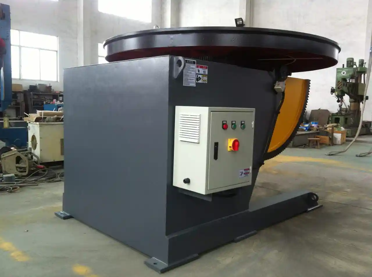
For circumferential seams on vessels and pipe spools, a Schweißen Drehtisch Lösungen platform is often paired with a column and boom manipulator. The rotator provides rotation while the manipulator positions the welding head. In this configuration, speed stability and anti-creep behavior directly influence weld quality. Precision linear guides and low-backlash reducers help maintain the seam under the welding arc.
In tank and vessel work, controlled rotation is what makes continuous girth welding possible. <Verbesserung der Qualität beim Schweißen von Rohren durch einen Hochpräzisions-Schweißpositionierer> covers the effect of controlled positioning on pipe weld consistency.
Safety integration is also part of the control system. ISO 12100 requires a risk assessment for machinery, and IEC 60204-1 sets the electrical safety requirements for machine controls [4][5]. For welding positioners, practical safety measures include emergency stop circuits, overload protection, anti-fall pins, and guarded control panels. In robotic cells, the positioner must be able to stop in a controlled state when an interlock is triggered.
Setup and Process Optimization for Large Components
Setting up a heavy-duty positioner correctly is as important as selecting the right model. The setup sequence should begin with the part’s center of gravity, proceed through clamping and balancing, and end with a dry-run rotation at low speed before welding.
A practical setup sequence includes:
- Mark the calculated center of gravity and align it to the table center where possible.
- Use calibrated fixtures, stops, and T-slot clamps to prevent movement during rotation.
- Check for interference at every planned tilt and rotation angle.
- Run a dry cycle at low speed and confirm the current path does not catch or twist.
- Record the final position values for repeat production.
For large-diameter circular seams, the welding speed must be matched to the positioner surface speed. A common issue is setting the rotator speed without translating it to linear welding speed. On a large vessel, even a small rotational speed change alters the linear speed at the torch. Use the formula below to maintain the correct value:
Linear weld speed = π × diameter × rotational speed
For example, a 3,000 mm diameter vessel rotating at 0.1 RPM produces a surface speed of approximately 0.94 m/min. If the welding procedure specifies 0.4 m/min, the positioner should be adjusted accordingly. This calculation must be part of the weld procedure qualification and production setup documentation.
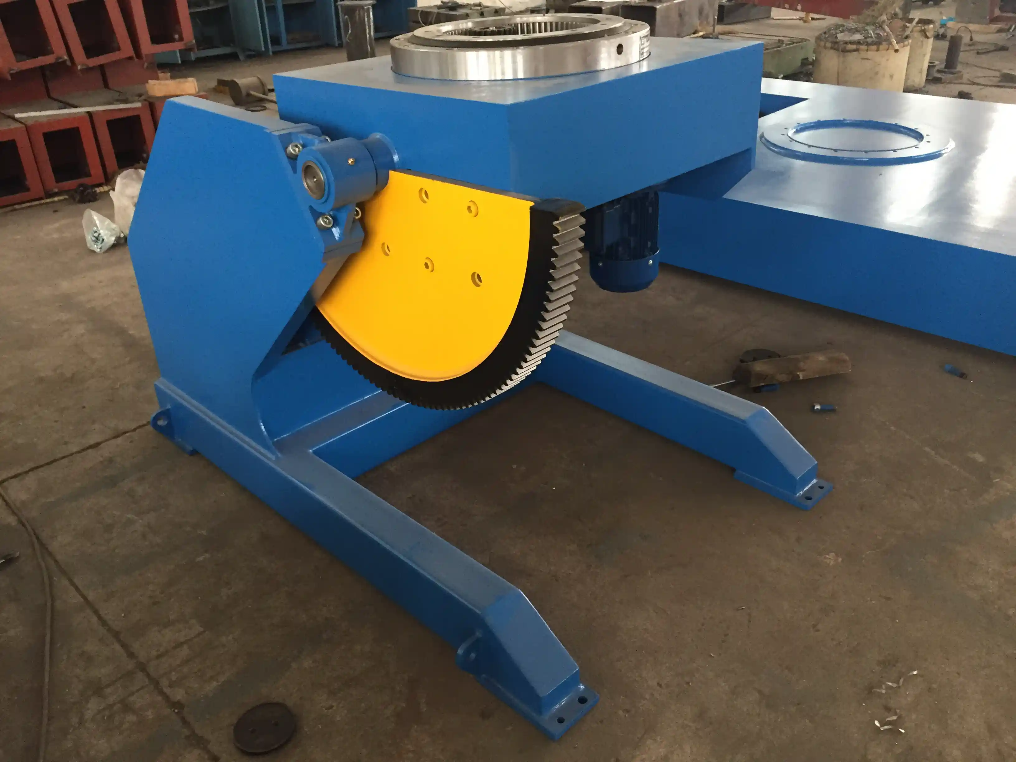
Wind tower sections and large cylindrical shells benefit from an Verstellbarer Schweißpositionierer or L-type configuration that supports the workpiece during rotation while providing easier access for longitudinal seams. The lifting function allows height changes between fit-up, root pass, and fill passes without re-rigging the part.
Common Problems and Their Causes
Heavy-duty positioning equipment can fail if the load, alignment, or drive system is outside design limits. The most frequent issues are:
- Wobble or runout. Causes include damaged slewing bearings, loose foundation bolts, or clamping on a non-flat surface.
- Uneven rotation. This can indicate worn reducers, backlash, or an overloaded drive.
- Tilt drift. Causes include hydraulic leakage or brake wear on tilt axes.
- Inaccurate repeat positioning. This often comes from encoder feedback fault, loose coupling, or exceeding the eccentric moment limit.
- Overheating or emergency stop faults. These may result from motor overload, poor ventilation, or excessive duty cycle.
When these symptoms appear, stop operation and verify that the part does not exceed the rated load and moment. Then check the mechanical components in the drive line: reducer, coupling, bearing, and brake. After maintenance, re-verify positioning accuracy before resuming production. Scheduled inspections should follow the manufacturer’s maintenance intervals for bearing lubrication, bolt torque, gear backlash, and electrical connection tightness.
Quality Assurance and Documentation
A welding positioner is part of the quality system, not just a material handling aid. ISO 3834-2 requires that welding-related equipment be suitable for the application and that records be maintained where necessary [1]. For structural steel under AWS D1.1, workmanship requirements include weld position, fit-up, and dimensional control [2]. For pressure equipment, ASME Section IX addresses procedure and performance qualification, while production positioning must support the qualified welding positions [3].
Documentation should record the positioner model, load case, setup drawing, weld map orientation, and any calibration results. For robotic cells, the positioner should have repeatability checks at scheduled intervals. This provides traceability when weld discontinuities are found and helps separate process problems from positioning problems.
| Documentation item | Typical content | Zweck |
|---|---|---|
| Load case | Part weight, center-of-gravity, eccentric moment | Confirm capacity |
| Setup drawing | Clamping points, support locations, tilt angles | Reproduzierbarkeit |
| Dry-run record | Interference check, speed settings | Process safety |
| Calibration record | Positioning accuracy, repeatability | Quality control |
| Maintenance log | Lubrication, backlash, torque checks | Equipment reliability |
These records are especially important for code work. An auditor may ask how a weld was positioned to confirm that the qualified range was not exceeded. A documented setup is strong evidence that the work was performed under controlled conditions.
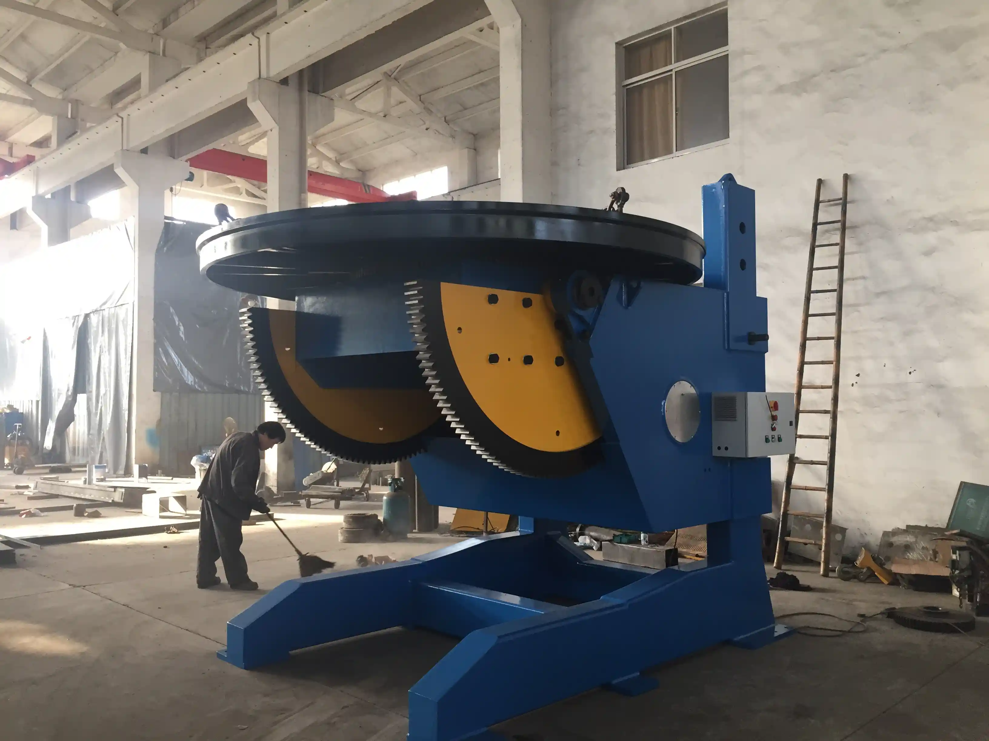
Request a Heavy-Duty Positioner Configuration Review
Every large fabrication job has a specific weld map, part envelope, and load case. WUXI ABK MACHINERY CO., LTD. can review your component drawings and recommend a positioner configuration based on capacity, table size, tilt range, control system, and automation interface. Send part drawings, weight, center-of-gravity dimensions, and the welding procedure to jay@weldc.com or call +86-13815101750 to discuss the application with a welding automation engineer.
FAQ
How do I choose the correct load rating for a heavy welding positioner?
Base the decision on the workpiece weight plus an eccentric moment calculation. The positioner must support the part at the maximum center-of-gravity offset required by the weld sequence, not only the weight at rest.
What is the difference between static load and dynamic load?
Static load is the part weight at rest. Dynamic load includes the additional force created by acceleration, deceleration, rotation, and the shifting center of gravity during tilt. A heavy-duty positioner should be rated for the worst expected load case.
Can a heavy-duty positioner work with a robotic welding system?
Yes. Many heavy-duty units include PLC control and robot interfaces for ABB, KUKA, FANUC, and Yaskawa controllers. The positioner becomes a coordinated external axis so the robot can weld while the part rotates.
What safety features should a heavy-duty positioner have?
Minimum requirements include emergency stop circuits, overload protection, mechanical anti-fall devices, guarded control panels, and controlled stopping through the machine control system. Electrical components should meet IEC 60204-1 and the machine should be assessed under ISO 12100 [4][5].
How often should positioning accuracy be verified?
Verify accuracy during commissioning, after any crash or overload event, and at scheduled maintenance intervals. Robotic cells may require more frequent repeatability checks because small positional errors directly affect weld location.
References
[1] ISO 3834-2:2021, Quality requirements for fusion welding of metallic materials — Part 2: Comprehensive quality requirements, International Organization for Standardization, Geneva, Switzerland, 2021.
[2] AWS D1.1/D1.1M:2020, Structural Welding Code—Steel, American Welding Society, Miami, FL, 2020.
[3] ASME BPVC Section IX, Welding, Brazing, and Fusing Qualifications, American Society of Mechanical Engineers, New York, NY, 2023.
[4] ISO 12100:2010, Safety of machinery — General principles for design — Risk assessment and risk reduction, International Organization for Standardization, Geneva, Switzerland, 2010.
[5] IEC 60204-1:2016, Safety of machinery — Electrical equipment of machines — Part 1: General requirements, International Electrotechnical Commission, Geneva, Switzerland, 2016.
Falls Sie daran interessiert sind, lesen Sie doch diese verwandten Artikel:
Die Schwerindustrie meistern: Wie kletternde Rollenböcke zum Grundstein für effizientes Schweißen werden
Übermäßige Fehlausrichtung beim Schweißen von Rohrleitungen: Präzisionspositionierungslösung mit dem Schweißdrehtisch von Wuxi ABK
Wuxi ABK Professionelle Rotationsschweißgeräte: Präzisionsschweißlösung für den Druckbehälterbau
Revolutionäre Lösung für das Schweißen von Druckbehältern: Technische Analyse von 360-Grad-Rotationsschweißpositionierern
Verbesserung von Qualität und Effizienz bei der Herstellung von Tanks und Druckbehältern: Der zentrale Anwendungswert von Positionierern
 English
  Español
  Français
  Deutsch
  Português
  Русский