
Tube-to-tube welding in pipeline construction is not just a joining step. It controls whether a piping system meets root quality, pressure integrity, and long-term service requirements. A careful weld procedure still fails in the field if joint preparation, alignment, or process selection does not match the tube material, wall thickness, and production conditions. This article examines the decisions that determine repeatable tube welds: preparation, welding method, rotator support, automation, and final acceptance.
Where Tube-to-Tube Welding Matters in Pipeline Construction
Pipeline construction includes long mainline girth welds, station piping, terminal skids, and prefabricated spools. Many of the most heavily inspected joints are tube-to-tube butt welds in small and medium bores, where access is limited and root defects are difficult to repair later. Applications range from carbon steel transfer lines to stainless steel instrument tubing, high-pressure hydraulic piping, and alloy heat exchanger circuits. In each case, the joint must be prepared so the selected process can fuse the root reliably under production conditions.
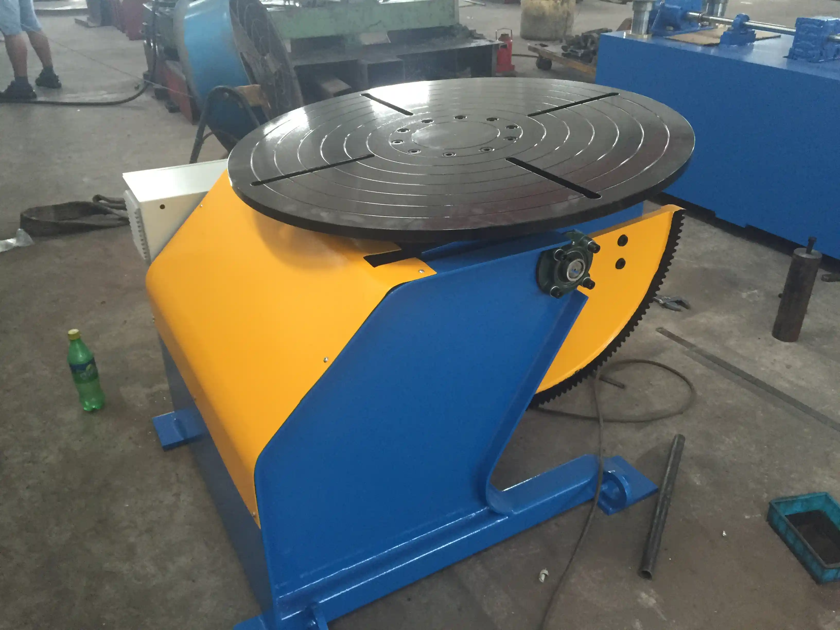
Why Joint Preparation Controls Tube-to-Tube Weld Quality
The first practical check is not the torch; it is the cut and fit-up. Root face, root opening, bevel angle, and cleanliness determine whether the welder can carry the weld pool through the root without excessive reinforcement or lack of fusion. For TIG and laser processes, fit-up must be tighter because the arc or beam is small. For MIG and flux-cored processes, a wider root may be tolerated, but only within the range qualified in the welding procedure. Mismatch also matters. A high-low condition forces the welder to choose between tying in the sidewall and controlling undercut or incomplete penetration.
Tack welds are part of preparation, not an afterthought. They hold alignment during fit-up and must be clean, placed within the future weld zone, and produced by qualified welders when the code requires it. For stainless and alloy tube, purge preparation is equally important. If the back side is not protected, oxidation can form even when the face looks acceptable.
High-low mismatch often shows up only after the root pass has already locked in the joint. <Probleme mit Ausrichtungsfehlern beim Schweißen von Rohren: Wie intelligente Schweißrohrrotatoren die Durchlaufraten von Ölpipelines erhöhen> covers how intelligent welding pipe rotators help control misalignment before welding starts.
How TIG, MIG, and Laser Compare for Tube Welding
No single tube-to-tube welding method is best for every pipeline application. TIG provides precise heat input and a clean root, but it is slower on thick-wall or large-bore production. MIG and pulsed MIG increase deposition and are easier to automate for carbon steel spools, but the operator or system must control fusion into both sidewalls. Laser welding produces a narrow heat-affected zone and high travel speed, but only when joint fit-up and beam-to-seam tracking are maintained. The choice is therefore a production decision, not a weld quality ranking.
| Decision factor | TIG | MIG or pulsed MIG | Laser |
|---|---|---|---|
| Heat input | Low and precise | Higher, with wider bead | Low and concentrated |
| Fit-up sensitivity | Hoch | Mäßig | Highest |
| Production speed | Unter | Hoch | Highest for thin-wall production |
| Root defect focus | Tungsten inclusion, root porosity | Lack of fusion, spatter | Porosity, mismatch sensitivity |
| Common use | Stainless and alloy tube, root-critical piping | Carbon steel spools, high-deposition joints | Thin-wall stainless or high-volume automated lines |
These differences do not replace weld procedure qualification. A shop should evaluate each method against the tube diameter, wall thickness, material, joint access, and the number of similar welds produced per shift.
How Alignment and Rotator Support Reduce Pipeline Weld Defects
Once the edge preparation is correct, the next risk is movement. Manual welding can tolerate small movement because the welder compensates, but mechanized and orbital welding cannot. A rotator or positioner supports the tube assembly and rotates it at a controlled speed so the torch stays in the flat or horizontal position. This improves torch angle, reduces operator fatigue, and keeps the weld pool from sagging on the root side.
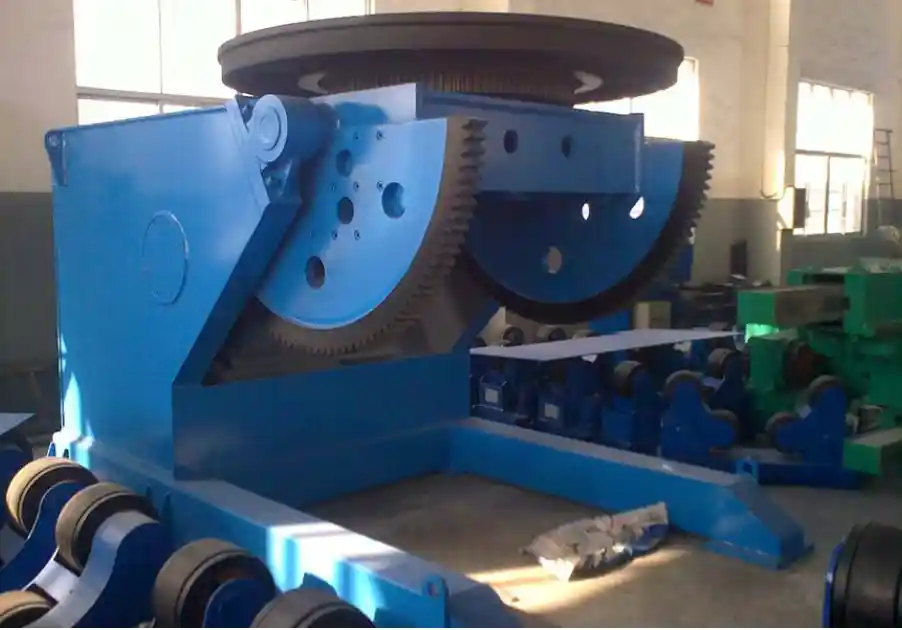
For small tubes, fixed-position welding may be practical when the joint is accessible from one side. For long spools, multiple girth welds, or heavy wall pipe, a fit-up rotator and tailstock can reduce setup time and help keep the tube centers aligned. Load capacity, roller spacing, and speed control must match the tube diameter and weight. A rotator that sags under load creates the same high-low condition the joint preparation was supposed to eliminate.
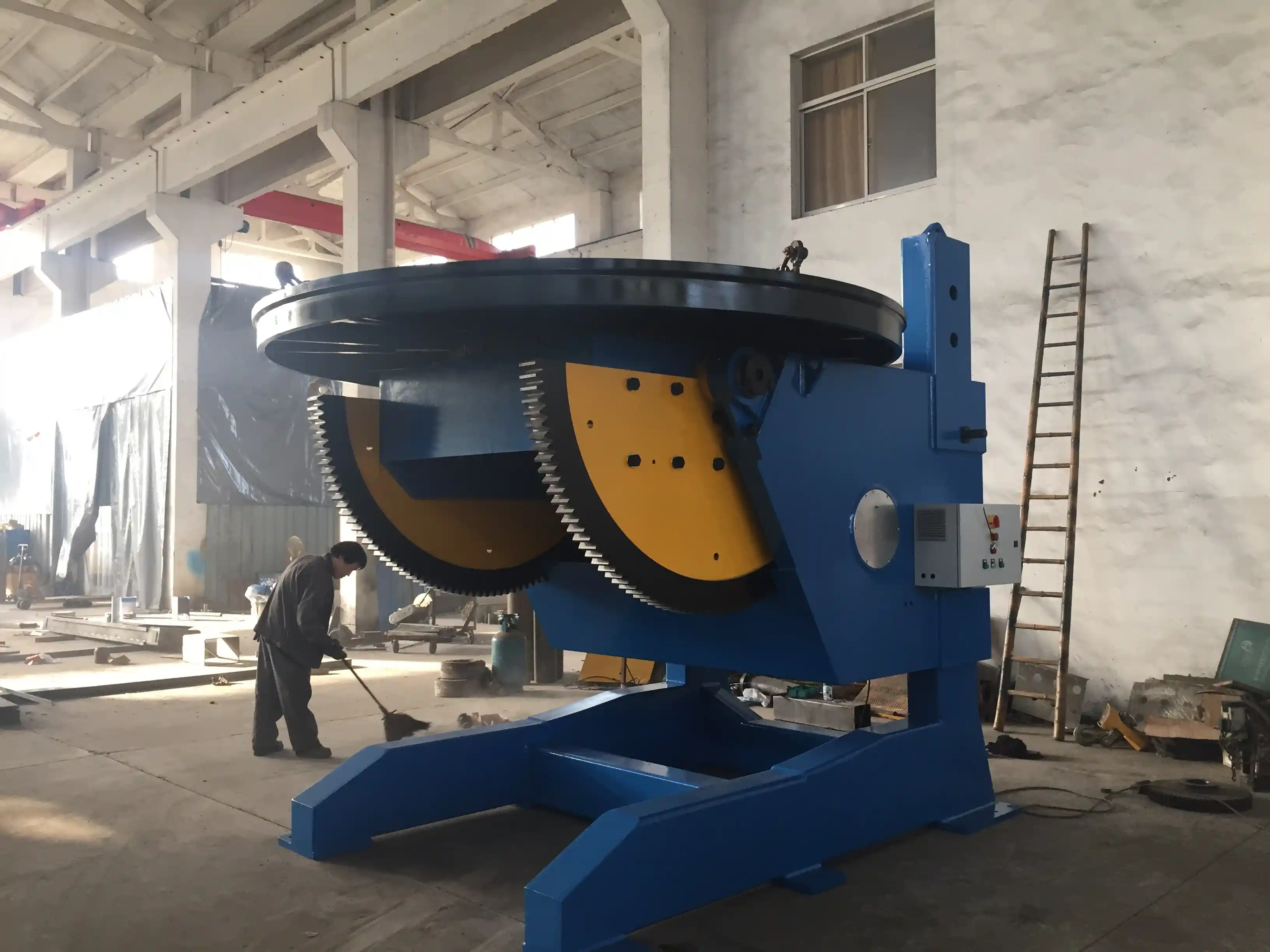
Heavy-bore pipeline spools follow the same principle as large vessel sections: the workpiece moves around a stable torch, not the other way around. That is why support equipment choice should be part of welding procedure planning, not a last-minute handling decision.
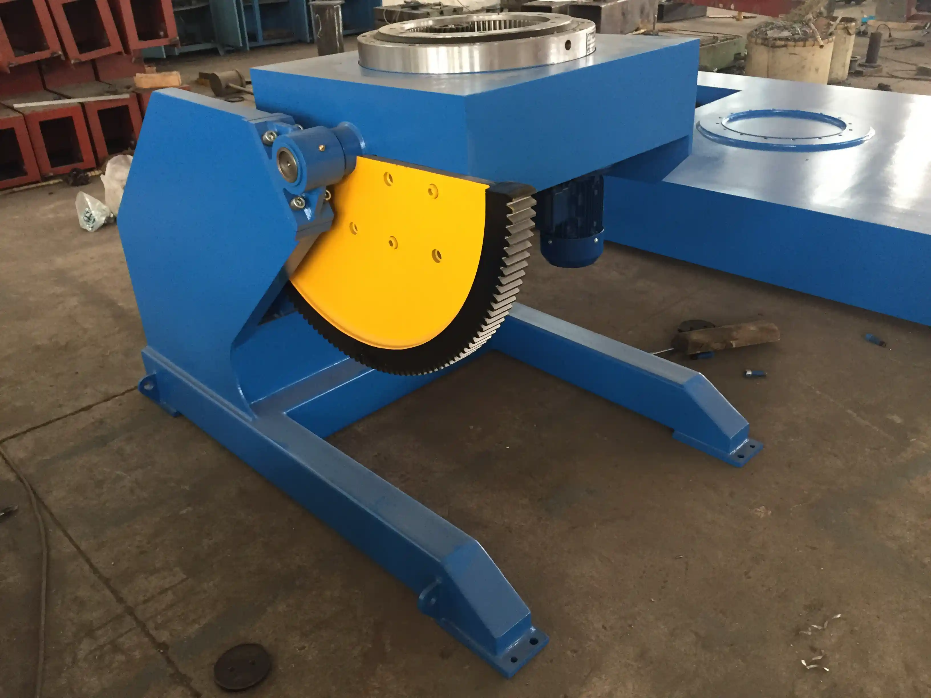
Consistent rotation keeps a long spool weld in the correct torch position and reduces the local variation that leads to uneven penetration. <Rohrrotatoren und Drehwalzen: Unverzichtbare Ausrüstungen für die moderne Pipeline-Fertigung> covers how turning rolls and pipe rotators support repeatable cylindrical and pipe welding.
Automation and Setup Considerations for Repeatable Tube Welds
Automated tube-to-tube welding becomes valuable when the same joint appears many times or when root quality must be documented. Orbital TIG systems control current, travel speed, wire feed, and torch position through a prequalified program. Seam tracking and arc voltage control help maintain torch-to-joint distance when the tube is not perfectly round. These systems reduce human variation, but they cannot correct bad fit-up, dirty material, or a poorly aligned joint.
Setup should begin with the weld procedure and the joint drawing, not with the machine program. Confirm the tube OD, wall, material, and end squareness; then select the purge flow, arc start position, and pulse schedule. For a shop producing multiple spool configurations, WUXI ABK configures tube-to-tube welding machines with compatible positioners and rotators so the workpiece support and torch travel are planned as one system. This reduces the chance that good welding parameters are undermined by poor joint access.
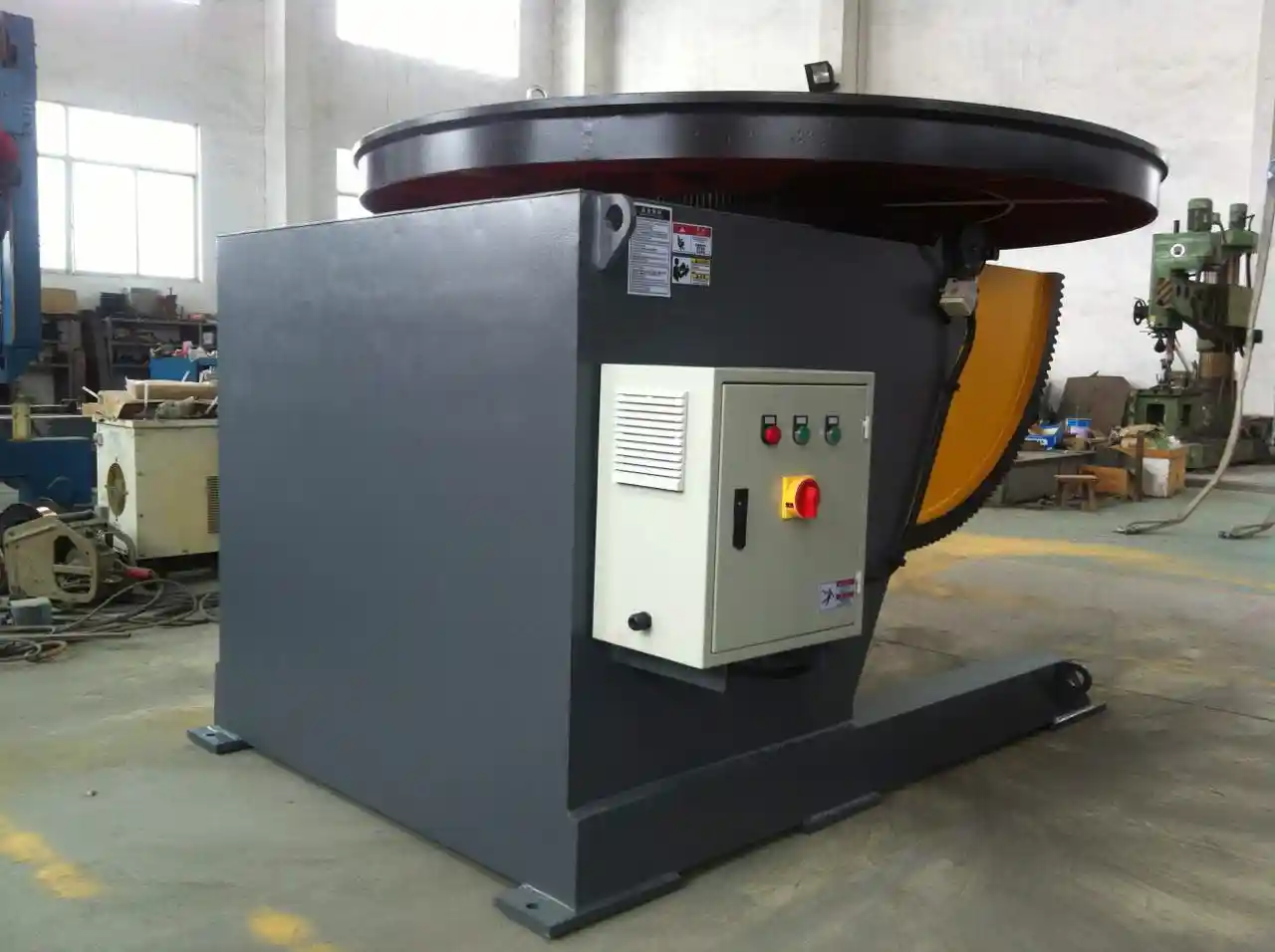
High-precision positioning is especially valuable when the same weld procedure must be repeated across a batch of spools. <Verbesserung der Qualität beim Schweißen von Rohren durch einen Hochpräzisions-Schweißpositionierer> covers how positioner accuracy influences pipe weld consistency and final inspection results.
Inspection and Acceptance Checks for Pipeline Tube Welds
Acceptance starts with the code or project specification. For process piping, ASME B31.3 establishes design, examination, and testing requirements [1]. For pipeline girth welds and related facilities, API 1104 is commonly used to classify and accept weld discontinuities [2]. Neither document supplies a universal fit-up number for every process; both direct the inspector back to the qualified welding procedure and the specified acceptance criteria. In practice, the weld is first checked visually for cracks, undercut, reinforcement, and surface porosity, then examined volumetrically when the service condition or code requires it.
| Inspection method | What it detects | What it does not cover |
|---|---|---|
| Visual | Surface cracks, undercut, reinforcement, cleanup | Internal defects |
| Liquid penetrant or magnetic particle | Surface-breaking discontinuities | Buried lack of fusion or porosity |
| Radiographic or digital radiography | Internal porosity, root condition, inclusions | Tight planar defects can be orientation-sensitive |
| Ultrasonic or phased array | Internal flaws, depth, and sizing | Requires qualified procedures and calibration |
For stainless tube, the root side also needs inspection or at least a clear purge procedure. A root that appears acceptable on the OD can still contain oxidation or incomplete penetration on the ID. The useful final check is not whether one weld looks good; it is whether the recorded weld matches the procedure, the fit-up report, and the NDT result.
Specify Your Tube-to-Tube Welding Requirements Before Ordering
Instead of starting with a generic tube welding question, send the joint information that drives the equipment decision: tube OD and wall thickness, material grade, joint type, welding process, production length per shift, and the code or standard the job must meet. We can then check rotator or positioner capacity, torch access, purge requirements, and the right level of automation with you.
Contact Zhang Jian at WUXI ABK Machinery Co., Ltd by email jay@weldc.com or phone +86-13815101750.
FAQ
Can one welding method cover all tube-to-tube joints?
Rarely. TIG suits root-critical stainless and alloy tube, MIG or pulsed MIG works well for carbon steel spools requiring higher deposition, and laser becomes attractive for high-volume thin-wall production. The method must follow the qualified weld procedure and match fit-up, purge, and inspection requirements.
How much root gap should a tube weld have?
There is no universal number. The WPS sets the range for the specified process and joint design. TIG and laser require tighter fit-up, while MIG open-root procedures may work with a controlled root face and gap. Check the prepared edge against the WPS before welding.
Do small-bore tube welds need a rotator or positioner?
Not automatically. A fixed-position weld may be practical when access is open and the weld is short. A rotator helps when the joint requires multiple passes, the torch angle is difficult to maintain, or the same production sequence repeats. Select the support based on tube weight, diameter, and weld position, not only the weld size.
What should be checked immediately before tube-to-tube welding?
Verify that the edge preparation matches the WPS, confirm squareness and mismatch, remove oil, moisture, and oxide, check the purge setup if the material requires back shielding, and inspect tack welds. If any of these conditions is uncertain, stop and correct it before the root pass.
How do we know a tube weld meets pipeline requirements?
Compare the completed weld against the code acceptance criteria and the project specification. That normally includes visual inspection first, followed by the NDT methods required by the code or service condition. A good visual appearance alone is not enough; documentation, fit-up records, and procedure qualification must also support the result.
References
[1] ASME B31.3, “Process Piping,” American Society of Mechanical Engineers, 2022.
[2] API Standard 1104, “Welding of Pipelines and Related Facilities,” American Petroleum Institute, 2021.
Falls Sie daran interessiert sind, lesen Sie doch diese verwandten Artikel:
Revolutionäre Lösung für das Schweißen von Druckbehältern: Technische Analyse von 360-Grad-Rotationsschweißpositionierern
Verbesserung von Qualität und Effizienz bei der Herstellung von Tanks und Druckbehältern: Der zentrale Anwendungswert von Positionierern
Präzisionsautomatisierung mit Schweißrotatoren für die industrielle Fertigung: Ein Leitfaden mit Fragen und Antworten von Experten
Außergewöhnlicher Anwendungsnutzen: Wie Schweißpositionierer mit fester Höhe den Fortschritt in der Offshore- und Schiffbauindustrie vorantreiben (Teil 2)
 English
 Español
 Français
 Deutsch
 Português
 Русский