A soldadura de torres eólicas line configuration that was selected without specific reference to tower section diameters, plate thicknesses, and production volume will create bottlenecks that no operator skill can overcome. I have reviewed multiple wind tower projects where the manipulador de soldadura lacked sufficient horizontal reach for the longest conical sections, or the positioner capacity was marginally rated for the top flange assembly, forcing the team to splice work between stations and lose half a shift per tower. The central principle is that every machine in the line from fit-up rotators to column and boom systems must be sized against the actual tower design specifications, not industry averages. This article outlines how to match equipment capacities, plan the station layout, and integrate the positioning and welding functions so the line delivers consistent output shift after shift.
Wind Tower Design Parameters and Their Direct Impact on Welding Equipment Selection
Wind tower sections are rarely simple cylinders. Most utility-scale towers consist of three to five conical sections, with base diameters commonly ranging from 4 meters to over 6 meters and plate thicknesses from 12 mm up to 60 mm or more for the lower sections. The first step in configuring a welding line is documenting the full dimensional envelope: minimum and maximum section diameters, shell length per section, plate thickness range, and the total mass of the heaviest individual segment including flanges and internal brackets.
These numbers translate directly into machine specifications. The horizontal travel of the welding manipulator must clear the full length of the longest section plus the clearance needed to withdraw the boom from the far end. For a tower section that measures 8 meters between flanges, a manipulator with 8 meters of horizontal stroke leaves no margin for changeover; in practice, we specify at least 500 mm of extra travel on each end for the boom to reposition without risk of collision. The vertical stroke dictates whether you can weld the top and bottom longitudinal seams in a single pass from a fixed column height, or whether the operator must re-index the section between passes.
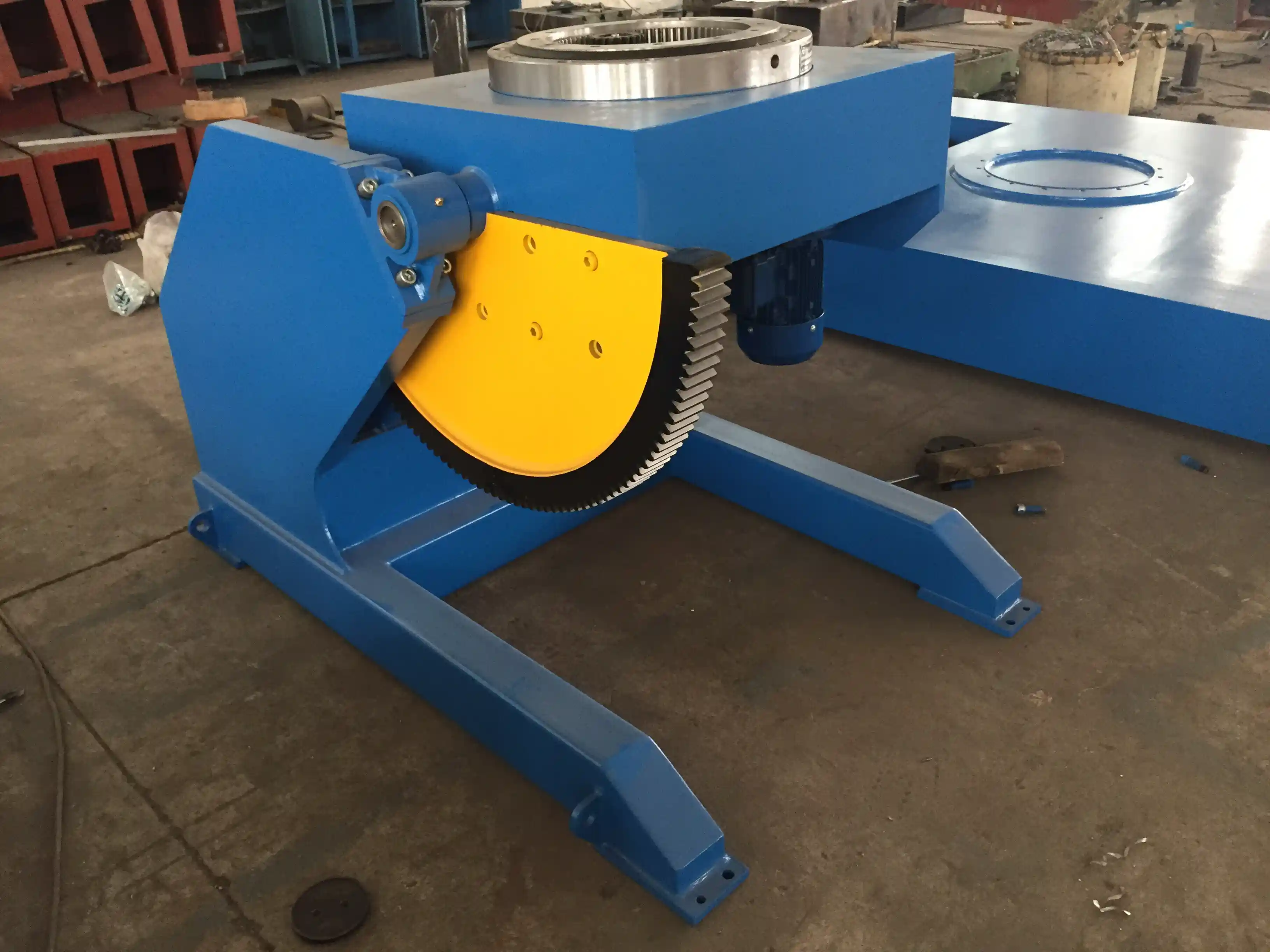
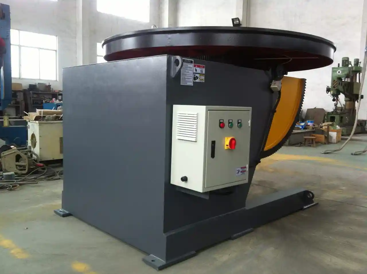
A tower base section weighing 40 tons requires a positioner with a static load rating that accounts for the center-of-gravity offset created by the conical shape. A standard L-type positioner rated for 30 tons may handle the total mass, but the overturning moment from an off-center cone section at 90-degree tilt demands a higher dynamic capacity. This is where we see many lines underperform: the load chart that came with the quotation was calculated for a symmetrical cylindrical workpiece, not a tapered shell with the mass concentrated toward the larger diameter.
| Tower Design Parameter | Equipment Specification Affected | Typical Range |
|---|---|---|
| Shell diameter (min-max) | Welding rotator wheel spacing and diameter range | 2.5 m – 6.5 m |
| Shell length per section | Welding manipulator horizontal travel | 4 m – 12 m |
| Plate thickness at longitudinal seam | Welding power source amperage and wire feed capacity | 15 mm – 65 mm |
| Heaviest section mass | Positioner capacity (static and dynamic) | 15 t – 80 t |
| Production volume per month | Number of stations, automation level, and cycle time | 20 – 80 towers |
Pairing the Welding Manipulator and Rotator for Longitudinal and Girth Seam Welding
The two primary weld types on a wind tower section are the longitudinal seam that closes the rolled shell, and the circumferential girth seams that join sections together. Most lines deploy a column and boom welding manipulator paired with a set of welding rotators or a head-tail positioner to handle both operations at dedicated stations. The manipulator carries the submerged arc welding head, flux recovery system, and often a seam tracking camera. The rotators turn the section under the torch at a controlled speed.
For the longitudinal station, the manipulator boom must have enough vertical travel to cover the full height of the section when it is positioned in a V-groove fixture or on a dedicated longitudinal welding bed. A boom elevating speed of around 0.4 meters per minute, combined with the horizontal travel speed during welding, determines whether the arc time per pass stays within the target cycle. The sections we configure for 4-megawatt towers typically require the LH8080 manipulator class because the 8-meter horizontal stroke and 8-meter vertical stroke accommodate the full length of the longest shells without repositioning the workpiece.
Circumferential welding stations combine the same manipulator type with self-aligning welding rotators sized for the section weight and diameter. For tower sections in the 30 to 60-ton range, the rotator pair must have a combined capacity well above the workpiece mass, and the roller diameter and spacing must prevent the conical section from walking axially during rotation. I have found that specifying the rotator wheel diameter at least 500 mm and adding a lateral guide roller on the idler frame reduces axial drift to less than 2 mm per revolution, which is tight enough to hold the root opening consistent without active seam tracking correction every pass.
Handling Conical Sections with Positioners and Fit-Up Rotators
Conical sections add a layer of complexity because the center of gravity shifts as the section rotates, and the welding torch must maintain a constant travel angle along a surface that is not parallel to the rotation axis. At the fit-up station, hydraulic alignment carriages on the fit-up rotators allow the operator to adjust the elevation of each end independently, bringing the seam edges into alignment before tack welding. Once the shell is rolled and tacked, it transfers to the welding station.
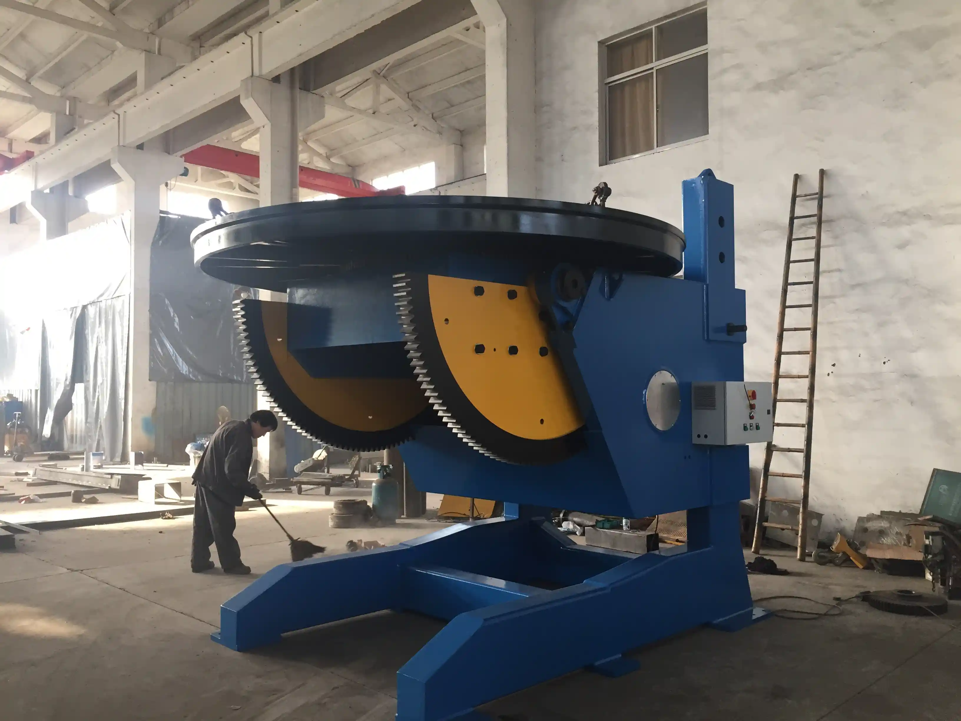
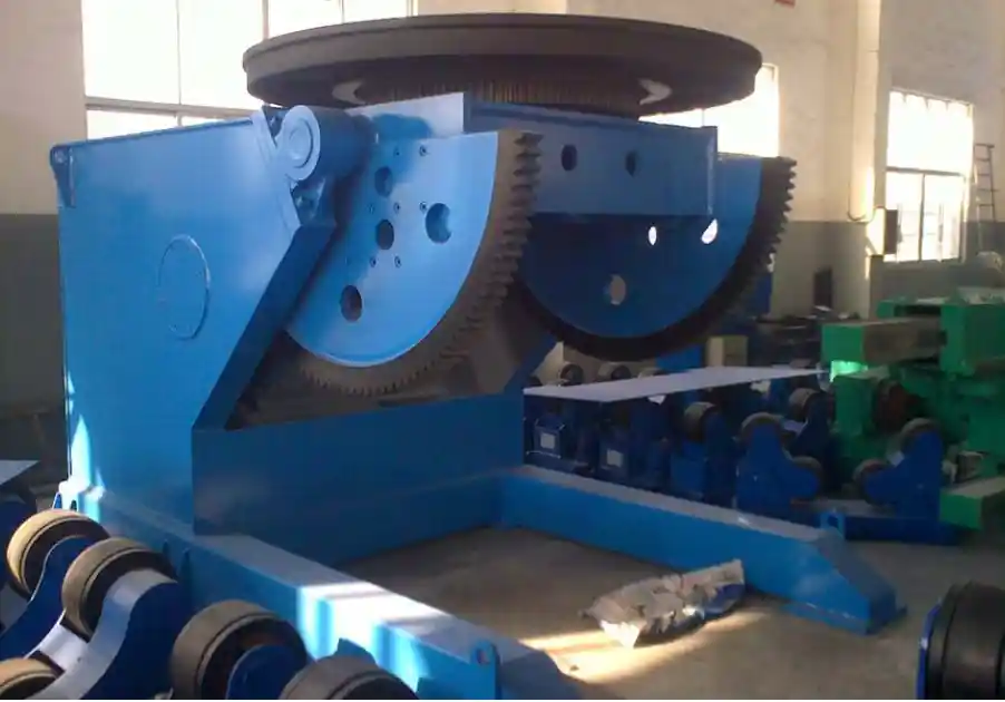
If you are producing towers with a significant taper ratio, a tilting positioner with 0-to-90-degree tilt capability and continuous 360-degree rotation becomes the more productive choice for the flange-to-shell and girth seam stations. The positioner holds the section by the flange or by a clamping fixture that engages the internal diameter. By rotating the entire section on the positioner, you eliminate the need for the rotator drive to overcome the variable diameter of the cone, which is a known source of speed fluctuation and weld defect risk.
WUXI ABK’s 30-ton adjustable height positioner with hydraulic lifting provides an example of a unit that can accommodate the elevation difference between the floor-mounted manipulator and the centerline of a large-diameter base cone. The 800 mm of height adjustment range makes it possible to keep the weld joint at the optimal torch-to-work distance without shimming the entire foundation. For the heaviest base sections of offshore towers, a 100-ton positioner with a worktable diameter of 1800 mm and a turnover angle up to 135 degrees enables complete access to both the internal and external root of the flange weld.
Laying Out Stations for Continuous Flow Without Buffer Starvation
A wind tower welding line that produces one fully welded section every shift requires four to five primary stations: plate edge preparation and bevel cutting, rolling and longitudinal seam welding, fit-up for girth welding, the girth welding station itself, and a dedicated station for internal bracket and door frame welding. The material flow should move in one direction, with each station sized to hold the workpiece for no longer than the cycle time of the slowest machine. A common mistake I see in first-generation lines is placing the longitudinal welding station at the end of the bay, which forces the heavy rolled shells to be transported back across the floor to reach fit-up, adding crane time and safety exposure.
The practical way to sequence is: the CNC cutting and bevel preparation station delivers plates to the rolling area, which feeds directly into the longitudinal seam welding station positioned at the head of the bay. From there, the rolled shell moves forward to the fit-up rotators, then to the flange welding positioner, and finally to the girth welding station where sections are joined. The boom manipulators are placed between the rails so the column can travel along a floor track that serves multiple stations. With the LH8080 manipulator’s trolley speed of 0.2 to 2 meters per minute, you can reposition the boom between the longitudinal and girth welding stations in under two minutes, which keeps the overall line balanced.
Buffer spaces between stations are necessary, but they must be physically defined with marked positions on the floor so that the crane operator knows exactly where to set each section. Without this, the stations drift and operators start walking between bays to locate the next piece. I recommend placing one buffer position after the longitudinal station and one after the fit-up station, with the remaining sections staged outside the immediate work zone until called forward.
Configuring the Line for Your Tower Specification Mix and Production Target
The most productive lines I have worked on are not the ones with the most automation, but the ones where every machine size matches the actual tower specs. If your tower range spans from 3-meter diameter tops to 6-meter diameter base sections, the welding rotator diameter range must cover all of them. The ABK adjustable welding rotator series, for example, offers models that handle vessel diameters from 250 mm up to 6,000 mm, but the specific model must be selected for the upper end of your range plus a margin. A 40-ton adjustable rotator with 450 mm wheel diameter and 500 to 4,800 mm vessel range covers most onshore tower sections, but the 60-ton model with 500 mm wheels and a 5,000 mm upper diameter is what we specify when the base cone exceeds 4.8 meters.
If you are building a line that must switch between 3-megawatt and 6-megawatt tower designs on the same equipment, the positioner and manipulator should be sized for the largest and heaviest section, and the workholding fixtures should be designed with quick-change adapters so that the clamp diameter can be adjusted within 30 minutes. This is where the project payback happens; a line that can run two different tower designs on alternate shifts with a single changeover per day delivers significantly more annual output than a line dedicated to one design that sits idle when order volume fluctuates.
If your program involves section weights above 80 tons or diameters exceeding 6.5 meters, the standard positioner and rotator catalogs may not cover the combination of load and tilt angle you need. In these cases, it is worth confirming the foundation requirements and the available lifting height in your building before finalizing the equipment specification. Reach out at jay@weldc.com or call +86-510-83555592 to discuss your heaviest section parameters and we can confirm the appropriate positioner and rotator ratings.
Equipment Selection Checklist for a Wind Tower Welding Line
The final output of a configuration exercise is a matched set of stations, but the selection process comes down to verifying each machine against the tower design spec sheet. I recommend running through each item below before issuing a purchase order.
- Confirm welding manipulator horizontal travel exceeds the longest shell length by at least 1,000 mm total (500 mm each end).
- Verify positioner dynamic load rating accounts for the overturning moment of the heaviest conical section at maximum tilt angle.
- Check rotator wheel spacing against the minimum section diameter to ensure both rollers contact the shell with sufficient wrap angle.
- Match the submerged arc welding power source amperage to the thickest plate in the production mix with at least 20% overhead.
- Plan the station sequence so material flows forward without backtracking, and define buffer positions explicitly.
- Size the girth welding station to handle the full assembled tower section weight if multi-section joining occurs in the line.
Matching Your Tower Dimensions to Practical Equipment Configurations
Equipment capacities on paper only become reliable production numbers when they are verified against your actual tower models. A 30-ton positioner that performs well with a 28-ton symmetrical workpiece may stall at the 90-degree tilt position when the center of gravity of a cone section sits 200 mm beyond the table centerline. I recommend asking your equipment partner to run a tilt test calculation based on your heaviest section’s CG coordinates before confirming the model. This is not a cost negotiation point; it is a production stability requirement that separates lines running at 85% utilization from those that need constant intervention.
For longitudinal seams, the boom forward speed range of 0.12 to 1.2 meters per minute on the manipulator must be evaluated against the welding procedure specification for the specific plate grade and thickness. S355 steel at 50 mm plate thickness with a single-pass SAW procedure may require a travel speed near the lower end, which drives a longer arc time. If your annual output target demands 40 towers, the longitudinal station must complete both internal and external passes within the shift window, which may necessitate a tandem wire setup or a second longitudinal station. The equipment capacity must be built around that time constraint, not just the physical dimensions.
When the tower line must accommodate multiple section designs, the flexibility of the positioner and rotator height adjustment becomes the limiting factor. A positioner with hydraulic lifting and 800 mm of travel, such as the 100-ton adjustable height model, allows the operator to raise or lower the workpiece centerline to match the manipulator boom height without scaffolding the column base. This reduces the changeover time between sections with different flange diameters to under 15 minutes, which translates into an extra section per week on a single-shift operation.
Frequently Asked Questions About Wind Tower Welding Line Configuration
How do I determine the right manipulator boom length for my tower sections?
Take the longest shell you will weld, add the distance from the column center to the section’s near edge, plus 600 mm for safe overtravel at both ends. Our LH8080 with 8000 mm horizontal travel works for most onshore tower sections up to about 7 meters shell length, but when the shells exceed that, a customized longer boom and extended rail system are usually the better option than repositioning the workpiece mid-weld.
What is the biggest mistake in wind tower welding line layout?
Placing the longitudinal seam station at the wrong end of the bay. When the station is not the first step after plate rolling, the crane must carry the heavy rolled shell across other active stations, which disrupts workflow and increases risk. I have corrected this layout on three retrofit projects, and the change alone improved daily output by roughly 20% because the stations stopped waiting for crane availability.
Can one welding line handle both onshore and offshore tower specifications?
Yes, but the equipment must be sized for the offshore tower requirements even if your initial production is onshore. Offshore tower base sections can exceed 8 meters diameter and 100 tons section weight, which demands a far heavier positioner and larger rotators than an onshore line. If you configure for the larger envelope from the start, running smaller onshore shells on the same machines is straightforward with the appropriate workholding adapters.
How do I ensure consistent weld quality on conical sections with varying wall thickness?
The submerged arc welding parameters must be programmed to change at specific axial positions along the cone if the plate thickness transitions within a single section. This requires a manipulator control system that can store multiple weld schedules and trigger them based on position feedback from the seam tracker. We configure the Siemens PLC system with pre-set parameter tables mapped to the tower design thickness profile so the operator loads the schedule for that section and the machine adjusts automatically.
What after-sales support should I expect for a wind tower welding line?
At minimum, the supplier should provide on-site commissioning, operator training, and a documented preventive maintenance schedule that covers daily, monthly, and annual tasks. Ask for a clear list of wear parts and their expected replacement intervals. For projects where the line is critical to a single large tower supply contract, we also recommend a service level agreement with guaranteed response times and remote diagnostic access. If your operation plans to run the line for multiple tower models over its lifetime, confirm that the supplier can provide retrofit kits for workholding and tooling changes.
What if my tower designs are still evolving and final dimensions are not locked?
Start with the worst-case envelope. Specify the largest diameter, heaviest section mass, and thickest plate you anticipate for the product roadmap, then add a 15% margin on load capacities and travel ranges. This front-loads a modest amount of capital cost while preventing the far more expensive situation of discovering two years later that the next tower generation no longer fits on the line you just installed. Share your design range and we can confirm a configuration that leaves room for growth; send your maximum expected dimensions to jay@weldc.com or call +86-13815101750.
Se estiver interessado, consulte estes artigos relacionados:
Melhorar a Qualidade e a Eficiência no Fabrico de Reservatórios e Recipientes sob Pressão: O principal valor de aplicação dos posicionadores
Wuxi ABK Professional Welding Rotary Equipment: Precision Welding Solution for Pressure Vessel Manufacturing
Problemas de desalinhamento na soldadura de tubos: como os rotadores inteligentes para soldadura de tubos aumentam as taxas de aprovação dos oleodutos
Manipuladores de soldadura para o fabrico de torres eólicas: Revolucionando a eficiência da produção
Desalinhamento excessivo na soldadura de condutas: Solução de posicionamento de precisão com plataforma giratória da Wuxi ABK Welding
 English
  Español
  Français
  Deutsch
  Português
  Русский