Custom tank welding equipment that matches the actual diameter and length of your vessels is not a luxury—it is the difference between a welding line that produces consistent, high-quality seams and one that requires constant manual repositioning, rework, and downtime. I have seen fabricators purchase well-known manipulador de soldaduras and rotators only to discover that the boom travel falls short of the full tank length or the roller capacity cannot handle the shell weight. The result is wasted capital and delayed projects. By specifying equipment with the correct reach, load rating, and rotational speed from the start, you eliminate these bottlenecks and create a production flow where each weld pass happens without interruption.
Limitations of Off-the-Shelf Tank Welding Equipment
Standard tank welding equipment from many suppliers is built around nominal vessel diameters and lengths. When your tanks range from 1.5 meters to 5 meters in diameter within the same shop, a single welding manipulator with a fixed 5-meter horizontal travel cannot cover the full welding length of the smaller tanks efficiently, and it may still be too short for the larger ones. I have visited fabrication shops where the manipulator’s boom could not reach the end of a 12-meter tank, forcing the crew to reposition the entire machine partway through a longitudinal weld. That manual repositioning introduces misalignment risk and increases cycle time by 20 to 30 minutes per seam.
Rotators present a similar challenge. A standard pipe rotator might accept a vessel diameter range of 250 to 2,300 millimeters, but if your production includes 3-meter diameter storage tanks, the rollers will touch the shell at an angle that invites creeping and side-slip. Off-the-shelf machines treat dimensional requirements as a fixed set, and any tank outside that envelope becomes a custom handling problem.
Key Tank Welding Equipment Components
A complete tank welding line relies on several core machines, each with specific dimensional requirements that must match your vessel size range.
| Tipo de equipamento | Primary Function | Key Specification for Tank Welding |
|---|---|---|
| Manipulador de soldadura | Longitudinal and circumferential seam welding | Boom length, vertical travel, rail travel distance |
| Rotador de soldadura | Shell rotation for girth welding | Load capacity, roller diameter and span, vessel diameter range |
| 3-Axis Welding Positioner | End cap, flange, and nozzle positioning | Load capacity, tilt range, table diameter |
| Máquina automática de soldar perímetros | Automated circumferential seam | Track diameter, travel speed, wire feed capacity |
| Sistema de elevação hidráulico | Shell alignment and elevation | Lifting capacity, stroke range, synchronization accuracy |
A welding manipulator with a column-and-boom design, such as the LH series we manufacture, combines horizontal travel, vertical boom lift, and optional column rotation. For tank work, horizontal travel determines how far the welding head can move along the length of the shell without relocating the entire carriage. Vertical travel must clear the highest point of the vessel when rotated. We have extended horizontal travel to 8,000 millimeters on LH8080 configurations to accommodate long storage tanks, while the compact LH3040 with 3,000-millimeter travel handles smaller boiler shells without wasting floor space.
Sizing Tank Welding Manipulators to Vessel Diameters
Selecting the correct horizontal travel starts with your maximum tank length plus at least 400 millimeters of over-travel at each end. If your longest tank is 10 meters, a manipulator with 9 meters of rail travel cannot complete a full longitudinal weld in one continuous pass. The welding head must exit the seam before the arc extinguishes; stopping short leaves a crater that becomes a defect.
Vertical boom stroke is equally critical. For tanks up to 4 meters in diameter, a vertical travel of 4,000 to 5,000 millimeters covers the full circumference when the vessel is positioned on rotators. We have integrated motorized carriage drives that synchronize with the rotator rotation speed, maintaining a constant welding velocity along the girth seam. On thicker shells, this synchronization prevents irregular bead width caused by gravity effects in the overhead position. When the boom length is miscalculated, the operator compensates by tilting the welding head, which alters the torch angle and penetration profile.
Selecting Tank Rotators and Positioners by Weight
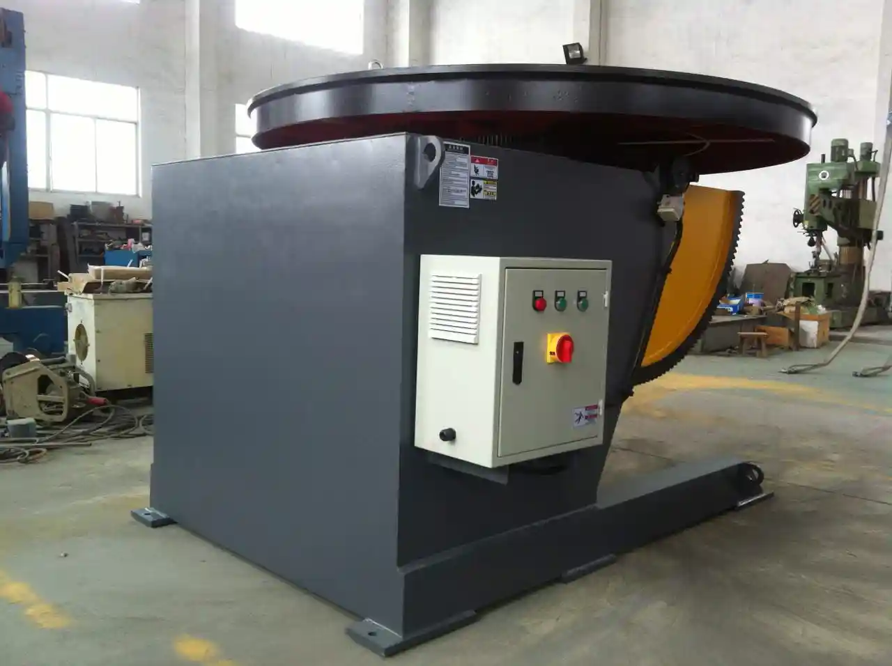
Rotator sizing is driven by shell weight, not just diameter. A 3-meter diameter tank with 12-millimeter wall thickness and 8-meter length weighs roughly 7.2 tons, but the rotator must also support the weight of the shell section plus the welding head pressure and any auxiliary equipment. A 10-ton rotator like the HGZ-10 provides a safe load margin and can adjust roller spacing to accommodate a 320-millimeter minimum and 2,800-millimeter maximum diameter. For larger tanks, the HGZ-40 handles up to 40 tons with a diameter range to 4,200 millimeters and uses self-aligning rollers that reduce creep to under 0.5 millimeters per revolution.
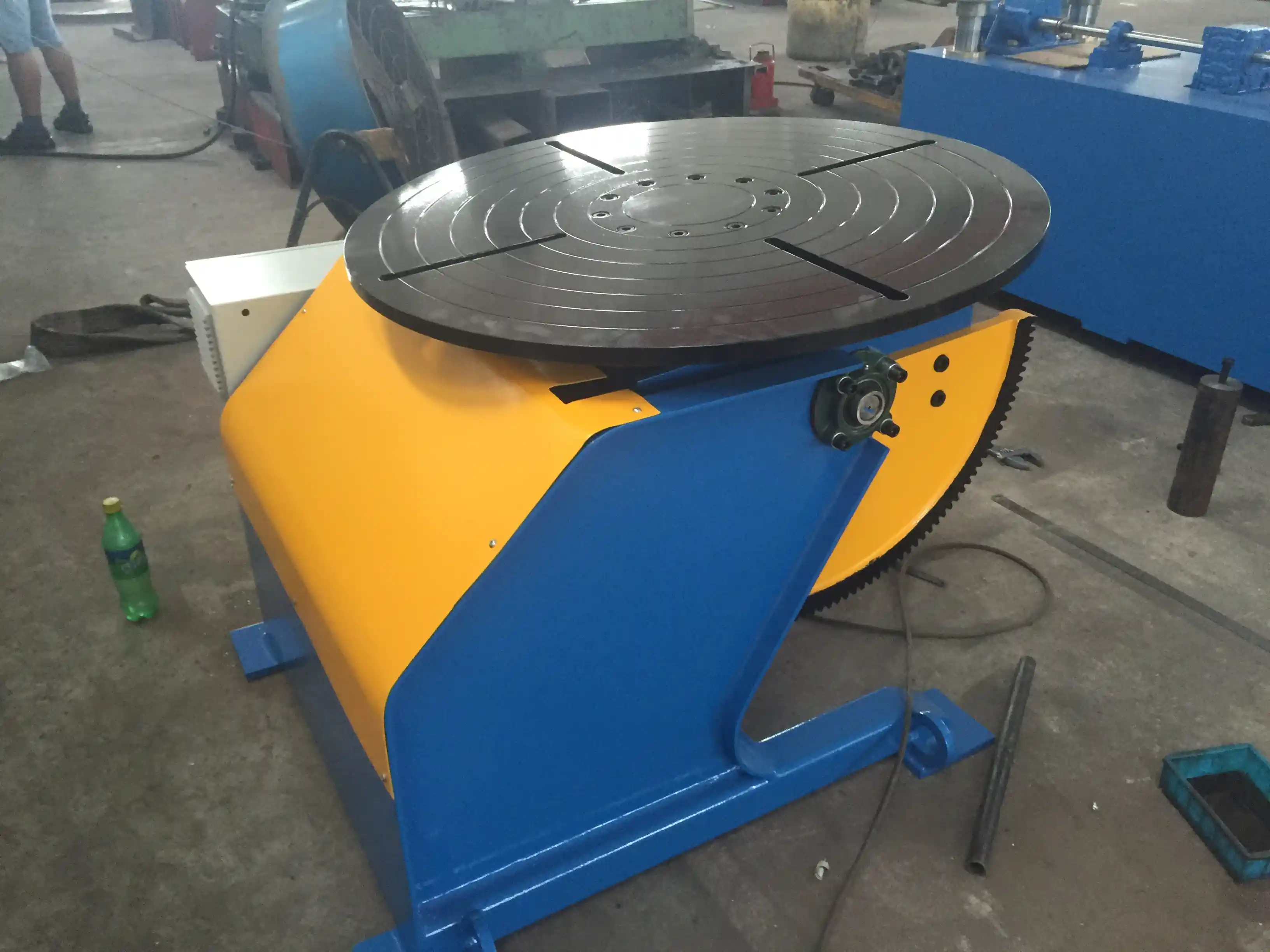
For end caps and flanges, a 3-axis welding positioner with 5-ton capacity, such as the LHBJ-50, supports tilting from 0 to 120 degrees and continuous 360-degree rotation. The L-shaped support arm provides clearance for protruding nozzles and fittings. In several projects, we have supplied positioners with a manual height adjustment range of 1,000 to 2,000 millimeters to let the operator level the workpiece precisely with the rotator line, preventing step misalignment between components.
If your vessel weights vary across projects — from 2-ton chemical tanks to 20-ton pressure vessels — a single fixed-capacity positioner or rotator becomes a bottleneck. We typically recommend a modular setup where the idle roller frame and driving roller are sized for the heaviest projected workload, while the manipulator boom and positioner table can be paired with lighter frames for smaller shells. This maximizes equipment utilization without overspending.
Configuring a Complete Tank Welding System
An integrated tank welding cell begins with the track layout for the welding manipulator. The rail system should allow full travel parallel to the vessel axis, with enough length for the manipulator base to clear the vessel ends during loading. We often specify an extra 2 meters of rail beyond the maximum vessel length for safe parking during crane operations. The rotator set — including one driving roller frame and one idle frame — is positioned on the shop floor at a height that aligns the vessel centerline with the manipulator’s torch oscillation midpoint. Hydraulic jacking systems can fine-tune elevation on uneven floors or when handling out-of-round shells.
For girth seam automation, an automatic girth welding machine mounted on a circular track around the rotator eliminates the need for the vessel to rotate. This is especially useful for extremely heavy tanks where rotation would require massive drive motors. We have supplied integrated cells where the same manipulator handles longitudinal seams while the girth welder operates independently on the next station, cutting total cycle time by nearly half compared to a single-station setup.
Customization extends beyond dimensions. Dusty environments call for IP54-rated electrical cabinets; stainless tanks benefit from flux recovery systems to maintain cleanliness; and shops with multiple tank designs may need programmable weld sequences stored in a PLC. The goal is a system that matches your vessel size range and your production rhythm, not a catalog specification that forces your workflow to adapt.
Common Questions About Tank Welding Equipment Sizing
Does the same welding manipulator work for both longitudinal and circumferential seams?
Yes, with proper setup. The manipulator performs longitudinal welds by traversing along the tank’s horizontal axis while the rotator holds the shell stationary. For girth welds, the rotator rotates the shell while the manipulator head positions at the seam and feeds wire at a controlled rate. The synchronization between rotation speed and wire feed rate determines bead consistency. A manipulator with a motorized cross-slide, like our LH series, can automatically adjust stick-out during rotation to compensate for slight ovality in rolled shells.
What happens if my tank diameter suddenly exceeds the rotator’s range?
The rollers will contact the shell too far apart, reducing the self-centering force and increasing the risk of the vessel walking sideways. In some cases, the shell may contact the roller base frame itself. We have added roller extension spacers and wider roller saddles to extend the diameter range on existing rotators for customers who added larger tanks to their product line. However, if the weight also increases beyond the load rating, a larger rotator set is the only safe solution. Checking your range before specifying a machine avoids this overload.
How long does custom tank welding equipment take to produce?
Production lead times depend on the extent of modification. Standard machines with minor travel or roller adjustments typically ship in 8 to 10 weeks from order confirmation. Fully custom manipulators with extended booms, additional axis drives, and custom control integration can take 14 to 16 weeks. Early engagement with our engineering team shortens the design review cycle because we work from your vessel drawings rather than iterating on generic assumptions. Send your tank specifications and production requirements to jay@weldc.com for a configuration proposal with a realistic timeline.
Se estiver interessado, consulte estes artigos relacionados:
Desafios da soldadura em torres eólicas: como os sistemas hidráulicos de elevação avançados aumentam a produção em 40%
O pilar central da produção pesada: O excelente desempenho dos suportes de rolos nos principais processos
 English
  Español
  Français
  Deutsch
  Português
  Русский