Pressure vessel fabrication is a positioning problem as much as a welding problem. Long shell courses, formed heads, nozzles, and internal attachments all require stable rotation, precise tilt, and controlled torch travel if the finished vessel is to meet code and fit-up tolerances. This guide breaks down the welding support equipment that has the greatest effect on pressure vessel quality and productivity: welding manipulators, positioners, rotators, and fit-up systems.
Why Pressure Vessel Welding Is Equipment-Sensitive
Unlike general structural welding, pressure vessel work is driven by joint geometry, wall thickness, preheat, and code requirements. ASME Boiler and Pressure Vessel Code Section VIII, Division 1 [1] requires demonstrated weld quality, joint preparation, inspection, and material traceability. The welding procedure may be correct on paper, but if a shell course cannot be held straight or rotated at the required speed, the weld process becomes inconsistent.
The equipment that supports the weld is often the difference between first-pass acceptance and repeated repairs. For a cylindrical shell, the main problems are:
- keeping the longitudinal seam at a stable torch angle;
- rotating the shell at a controlled surface speed for girth seams;
- holding dished heads and nozzle stubs in the correct welding position; and
- maintaining alignment between shell courses during fit-up.
This is why a pressure vessel shop typically buys more than a welding power source. It invests in a coordinated set of positioning and handling machines.
Core Equipment for Pressure Vessel Fabrication
Welding Manipulators for Longitudinal Seams
A column-and-boom welding manipulator carries a submerged arc, MIG/MAG, or flux-cored welding head along the length of a vessel shell. For pressure vessel work, the manipulator should provide:
- horizontal travel long enough to pass the full seam without stopping;
- vertical travel to reach different vessel diameters or rotate the boom into position;
- speed control matched to the welding process; and
- rigid guideways to reduce torch deflection.
Standard column-and-boom units for pressure vessel shops often range from 3 m to 8 m of horizontal travel and 4 m to 8 m of vertical travel, with ±180° rotation. Positioning accuracy around ±0.1 mm/m helps keep the arc on the joint over a long seam. If the shop welds shells of varying diameter, the vertical range matters as much as the horizontal stroke.
Welding Positioners for Heads, Nozzles, and Vessel Sections
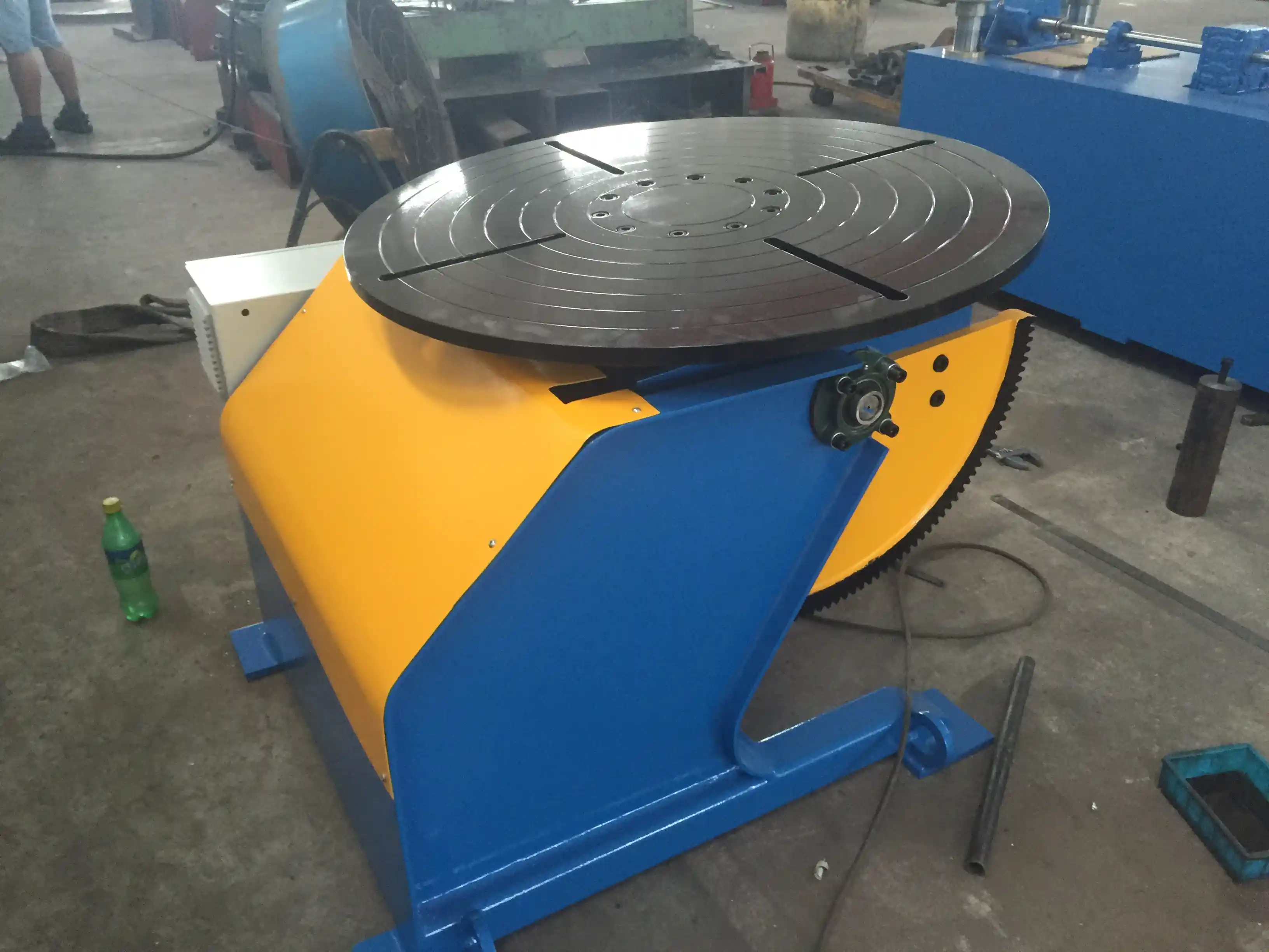
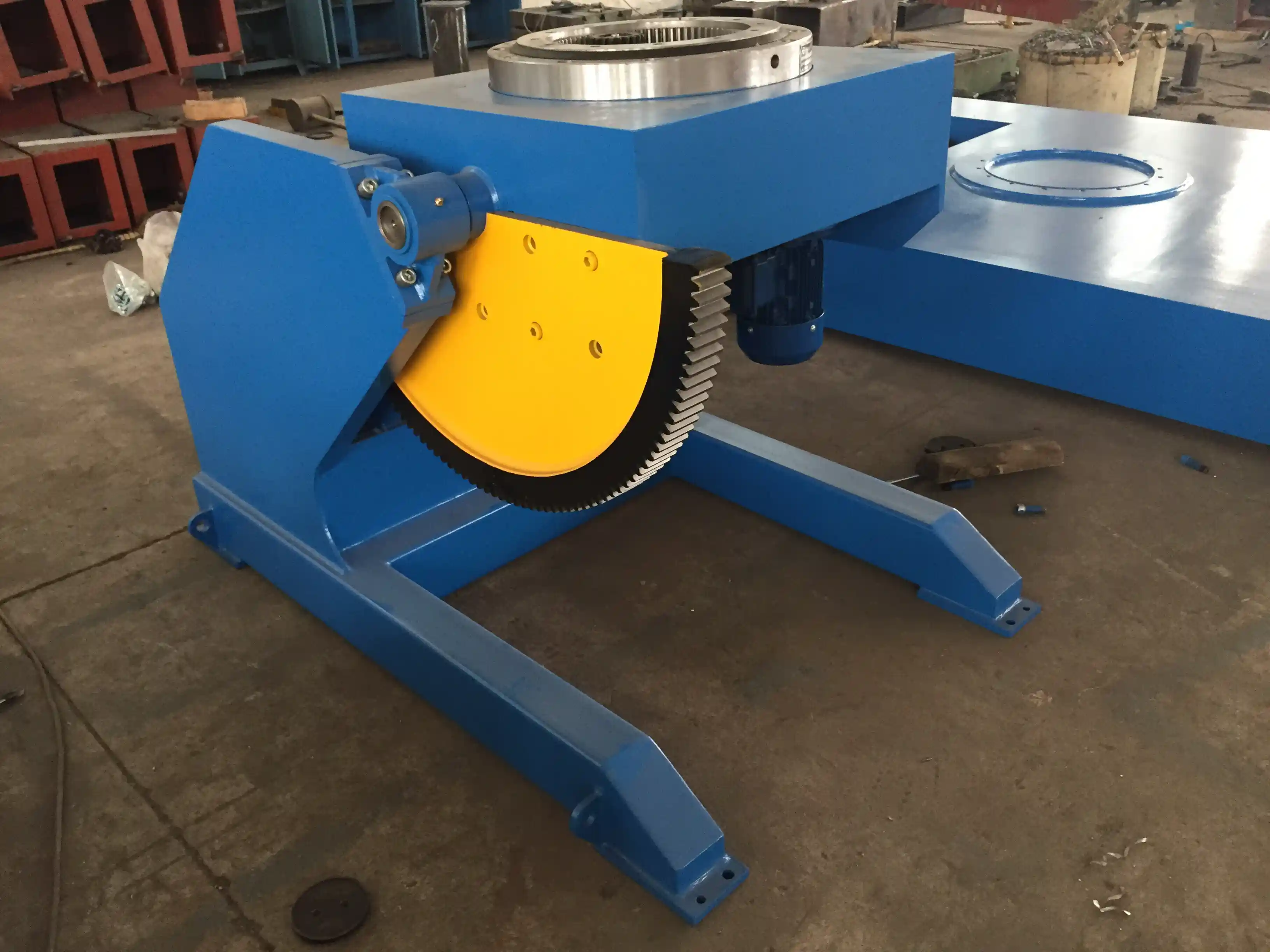
A 3-axis welding positioner uses rotation, tilt, and turning axes to put a workpiece in the best welding position. For pressure vessel fabrication, positioners are used for:
- dished heads and flanges;
- nozzle and manway assemblies;
- small vessel sections; and
- robotic welding cells where the part must be presented to a fixed robot.
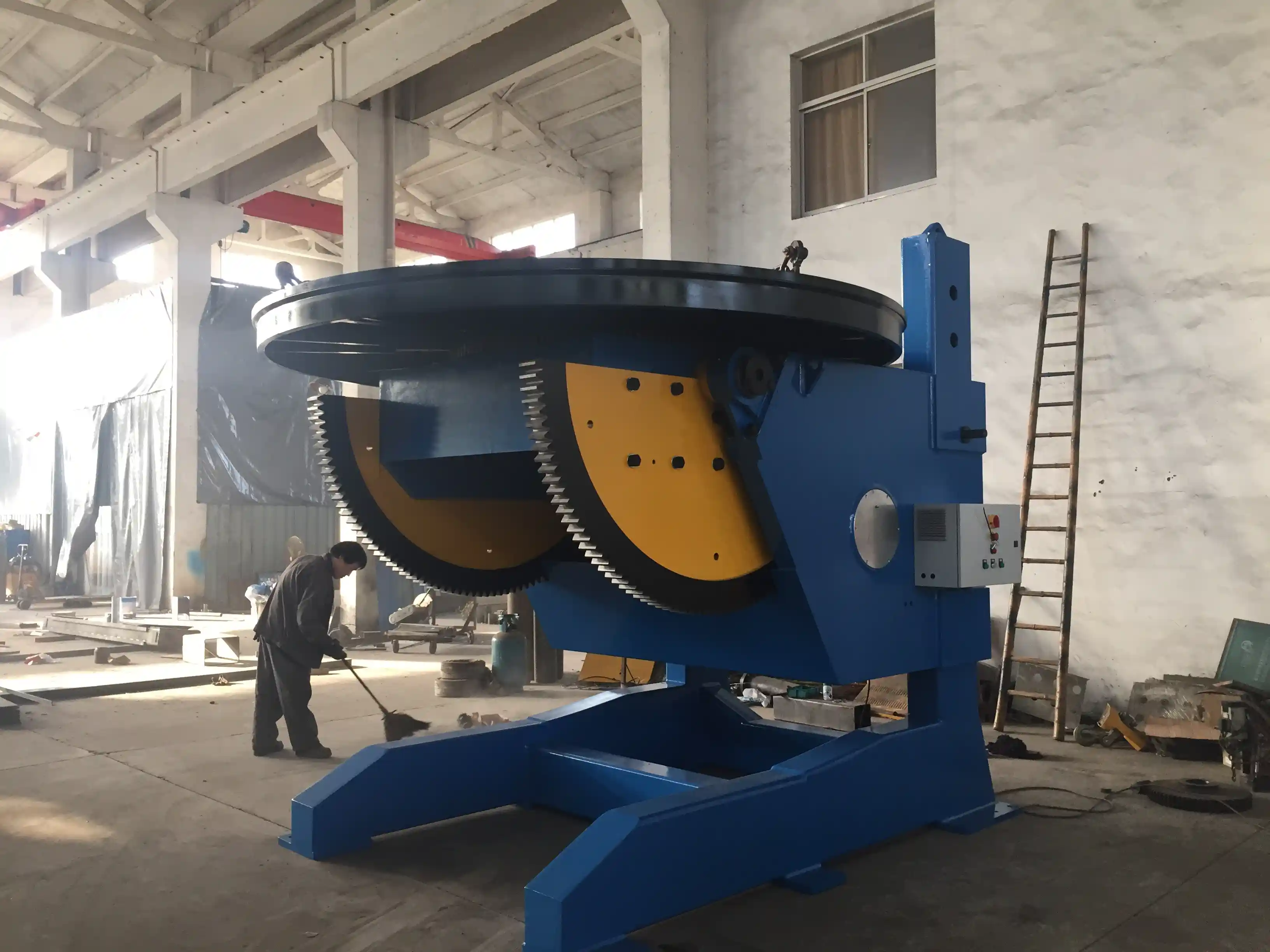
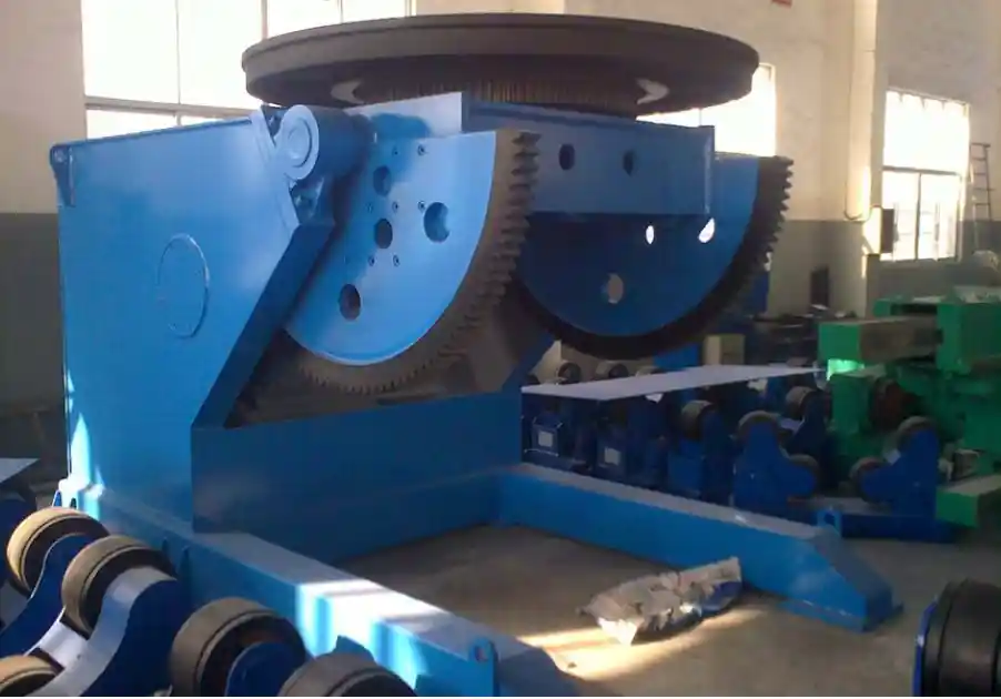
Typical fixed-height positioners for pressure vessel components range from 1-ton to 5-ton capacity with table diameters around 1,200 mm to 1,500 mm. Heavier L-type or adjustable-height positioners extend capacity to 30 tons, 50 tons, or 100 tons for thick-wall vessel sections. Key features are conductive slip rings for continuous rotation, a PLC or HMI control interface, and overload protection. When evaluated for a pressure vessel head, the center-of-gravity distance and eccentric load rating matter more than the raw table capacity.
On circumferential seams and end closures, controlled rotation is as important as heat input. <Revolutionary Solution for Pressure Vessel Welding: Technical Analysis of 360-Degree Rotating Welding Positioners> covers how 360-degree rotating positioners improve weld access and consistency on pressure vessel joints.
Welding Rotators and Fit-Up Systems for Shell Courses
Long cylindrical shells are rotated by pipe rotator equipment during girth welding. Welding rotators provide support on both sides of the shell and rotate it at a controlled surface speed. For pressure vessels, rotator selection depends on vessel diameter, wall thickness, and total loaded weight.
Standard and adjustable-height rotators range from 5 tons to 300 tons, with vessel diameter coverage from about 250 mm to 6,000 mm depending on the model. Adjustable-height designs allow the driving and idler roller centers to be set so the shell rotates without creeping. For heavy wall courses, the following are essential:
- self-aligning rollers;
- anti-creep control;
- hydraulic or manual height adjustment; and
- speed regulation matched to submerged arc or MIG/MAG travel speed.
For fit-up of shell-to-shell girth seams, dedicated fit-up rotators align the two shell ends before welding. Hydraulic alignment carriages, laser guidance, and clamping help control high-low mismatch and root gap. The target is not only rotation but consistent joint presentation.
After fit-up, long vessel courses need stable turning. <Pipe Rotators and Turning Rolls: Essential Equipment for Modern Pipeline Fabrication> covers how turning rolls support cylindrical workpieces through girth and longitudinal welding.
If vessel diameter, shell length, and wall thickness are already known, email jay@weldc.com with the main dimensions. The load case, rail spacing, and roller center distance can be checked directly before equipment is selected.
Matching Equipment to Vessel Size and Production Volume
Equipment selection should be based on the largest critical vessel, not the average job. The table below provides a practical starting point.
| Vessel or workpiece | Recommended equipment | Typical capacity or working range |
|---|---|---|
| Small heads, nozzles, flanges | Fixed-height welding positioner | 1–5 t capacity, 1,200–1,500 mm table diameter |
| Shell courses 0.3–3 m diameter | Standard pipe rotator or adjustable rotator | 5–20 t capacity, approximately 250–4,500 mm diameter |
| Medium vessels 3–5 m diameter | Adjustable-height welding rotator plus fit-up system | 20–60 t capacity, 500–6,000 mm diameter depending on model |
| Long straight shell seams | Column-and-boom welding manipulator | 3–8 m horizontal travel, 4–8 m vertical travel |
| Heavy vessel sections and large heads | Adjustable or L-type welding positioner | 30–100 t capacity, with tilting and 360° rotation |
These ranges are representative. The final selection must account for combined weight, center of gravity, eccentricity, wheel spacing, and available floor area.
For projects involving vessels over 30 tons, thick-wall sections, or multi-pass submerged arc welding, provide the shell drawing to WUXI ABK early at jay@weldc.com or +86-13815101750. A direct inquiry is the shortest way to confirm whether a standard positioner or a configured manipulator-plus-rotator set will fit the load case and joint access.
Automation, Controls, and Inspection Access
Modern pressure vessel equipment is not just a set of mechanical axes. PLC and HMI controls, encoder feedback, and preset programs allow the operator to set rotation speed, tilt angle, and travel limits for repeatable weld passes. Many 3-axis positioners can be used as external robot axes with ABB, KUKA, FANUC, or Yaskawa systems. This is especially useful for nozzle welds, where a robot or a fixed boom needs consistent part presentation.
Seam tracking, arc voltage control, flux recovery, and fume extraction can be integrated into the same workcell. For pressure vessel welds, the control system should also:
- hold travel speed within the qualified welding procedure;
- provide jog and inch modes for fit-up;
- record basic parameters or at least maintain consistent settings; and
- stop safely on overload, emergency stop, or torch collision.
Automation does not eliminate the need for qualified procedures. Weld procedure qualification to ISO 15614-1 [2] and welder performance qualification remain the baseline. AWS D1.1 [3] is often referenced for structural supports, lugs, and temporary attachments. The automation equipment supports those qualified procedures by keeping the welding speed, torch angle, and preheat positioning stable.
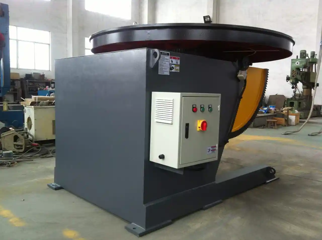
For shops adding robotic welding to pressure vessel components, specify a positioner with servo-driven axes, good repeatability, and a controller that can interface with the robot. Gravity and inertia on thick-wall heads can be substantial, so the positioner should not be selected at maximum load rating for a high-volume robotic cell.
Common Equipment Mistakes That Delay Pressure Vessel Projects
The most expensive mistakes usually appear before the first arc is struck.
- Selecting positioners by nominal weight alone. A 5-ton positioner may not handle a 4.5-ton head with a large eccentric distance or high center of gravity.
- Ignoring shell walk or creep on rotators. Poor roller spacing and alignment cause the shell to move axially during welding, which creates overlap and undercut.
- Underestimating fit-up time. Without a fit-up rotator or alignment system, shell-to-shell joints consume too much crane time and produce high-low mismatch.
- Choosing a manipulator with insufficient vertical travel. Different vessel diameters can put the boom at the wrong height, forcing manual setup changes.
- Forgetting preheat and inspection access. The equipment must permit preheat torches, temperature checks, and NDT access without removing the workpiece.
- Over-automating a low-volume shop. For one-off vessels, a flexible positioner plus a standard manipulator often performs better than a dedicated hard-automated line.
Each of these issues can be avoided by defining the load case, joint access, quality requirement, and production volume before purchasing.
Plan Your Pressure Vessel Welding Line Around the Load, Not Just the Welder
For code-compliant pressure vessel fabrication, the welding power source is only one part of the system. The right combination of welding manipulator, positioner, rotator, and fit-up system determines whether long seams stay straight, girth seams stay aligned, and heads are presented at the correct angle.
If you are configuring a new pressure vessel line or upgrading an existing one, have shell diameter, length, wall thickness, material grade, and production target available. Contact WUXI ABK at jay@weldc.com or call +86-13815101750 to discuss the project. WUXI ABK supplies welding manipulators, 3-axis positioners, fixed-height and adjustable-height positioners, pipe rotators, and fit-up systems for pressure vessel and heavy fabrication applications.
FAQ
What is the most important equipment for pressure vessel fabrication?
Most pressure vessel shops need a combination of a welding manipulator for longitudinal seams, a welding positioner for heads and nozzles, and welding rotators for shell courses. The exact priority depends on vessel size and product mix, but positioning equipment has the greatest effect on weld consistency.
How do I choose between a welding positioner and a welding rotator?
Use a welding positioner when the workpiece needs rotation plus tilt, such as a dished head, flange, nozzle, or small vessel section. Use a welding rotator when long cylindrical shell courses need rotation for girth welding while remaining horizontal.
What load capacity should I select for a shell section?
Select based on total loaded weight plus the center-of-gravity distance and eccentricity, not nominal gross weight alone. A conservative approach is to add a 20–30% margin for dynamic loads, clamping, and future job mix.
Can these systems be used with robotic welding?
Yes. Modern 3-axis positioners with PLC and HMI controls can serve as external axes for ABB, KUKA, FANUC, or Yaskawa robots. The positioner must have servo-driven axes, sufficient repeatability, and a compatible control interface.
What standards apply to pressure vessel welding?
ASME BPVC Section VIII, Division 1 is the primary code for many pressure vessel projects. Welding procedure qualification is commonly performed to ISO 15614-1, with AWS D1.1 referenced for structural attachments. Always follow the project specification and local regulations.
References
[1] ASME Boiler and Pressure Vessel Code, Section VIII, Division 1, Rules for Construction of Pressure Vessels. American Society of Mechanical Engineers.
[2] ISO 15614-1:2017, Specification and qualification of welding procedures for metallic materials — Welding procedure test. International Organization for Standardization.
[3] AWS D1.1/D1.1M:2020, Structural Welding Code—Steel. American Welding Society.
If you’re interested, check out these related articles:
How to Improve the Quality of Pipe Welding Through a High-Precision Welding Positioner
Wuxi ABK Professional Welding Rotary Equipment: Precision Welding Solution for Pressure Vessel Manufacturing
 English
  Español
  Français
  Deutsch
  Português
  Русский