
Steel structure fabrication starts with cutting accuracy. Columns, beams, base plates, stiffeners, gussets, end plates, and connection details must match the shop drawing within tight tolerances, because every downstream operation—fit-up, tack welding, full welding, straightening, and final inspection—is affected by the quality of the cut edge. CNC cutting machines close the gap between design model and physical part by converting CAD/CAM geometry into repeatable torch or beam motion.
The practical decision is to match the cutting energy source, table capacity, torch configuration, control system, and quality verification method to the actual steel mix in the shop. A machine that works well for 10 mm gusset plates may be the wrong choice for 80 mm column base plates, or for stainless steel components that require a clean edge with minimal heat tint.
This guide focuses on the engineering decisions that matter in steel structure fabrication: technology selection, thickness capability, programming and nesting, weld preparation, material flow, and supplier evaluation.
Where CNC Cutting Fits in Steel Structure Fabrication
In structural fabrication, parts rarely arrive as simple rectangles. Beam copes, fish plates, gusset plates, splice plates, end plates with hole patterns, stiffener profiles, and weld access holes all require profile cutting. Manual layout and hand torch cutting introduce variation at nearly every step. CNC cutting replaces scribing and hand positioning with programmed geometry, kerf compensation, and repeatable tool paths.
The first quality reference for structural cut parts is ISO 9013, which defines geometry product specifications and quality tolerances for thermally cut surfaces. A fabricator can specify cut quality not as “clean” or “smooth,” but as a tolerance class for perpendicularity, surface roughness, profile deviation, and edge rounding [1]. This becomes especially important when parts are later joined by welding.
CNC cutting also supports part identification and traceability. The controller can mark piece numbers, assembly zones, and heat numbers directly on the plate during the cutting cycle. Where required by the fabrication execution class, traceability records must connect a cut part to the original material certificate and to the welding quality documentation [2].
Matching the Cutting Process to Plate Thickness and Material
The most important selection factor is not the machine brand but the energy source. For carbon steel plate used in structural fabrication, three processes dominate: plasma, flame, and laser. Water jet and high-power laser cutting occupy specific niches when the material is stainless steel, aluminum, or when heat input must be minimized.
The following comparison is a general starting point. Process limits depend on amperage, laser power, gas type, plate grade, and surface condition.
| Process | Common Steel Thickness Range | Edge Quality in Structural Work | Typical Use in Steel Fabrication |
|---|---|---|---|
| CNC plasma cutting | 3–50 mm | Good to very good; moderate HAZ | Beams, gussets, base plates, long profiles |
| CNC flame cutting | 10–300 mm | Good on thick plate; slower | Column base plates, heavy splice plates, bevels |
| CNC laser cutting | 1–30 mm | Excellent; narrow kerf, low HAZ | Thin gussets, shims, architectural details |
| CNC water jet cutting | 5–150 mm | Excellent; no HAZ | Stainless, aluminum, heat-sensitive alloys |
The thickness ranges above are typical industrial envelopes, not absolute machine limits. Actual capability must be verified with the specific plate grade and cut quality class required by the project.
For many steel structure shops, the practical configuration is a multi-process bay: one heavy-duty CNC flame cutting machine for thick plate and weld preps, and one CNC plasma cutter for high-speed profile work. Where the shop also produces thin stainless or architectural components, a CNC laser cutting machine adds value. A CNC water jet cutting machine is justified when the product mix includes materials that cannot tolerate a heat-affected zone.
For shops moving from manual layout to CNC, the fastest way to validate a system is to send a small set of production drawings and request a trial nest on the actual steel grades used in the shop. The technical review should also cover bridge crane clearance, fume extraction capacity, duty cycle, and whether the controller can accept existing nesting files. For a specification review and cutting trial, contact jay@weldc.com or +86-13815101750.
Programming, Nesting, and Dimensional Control
Accurate parts begin before the torch fires. Modern CAD/CAM software converts the detailing model into tool paths, applies kerf compensation, and assigns lead-ins and lead-outs. Without correct kerf values, a part program is not a true representation of the finished component. The controller should also compensate for thermal distortion on long narrow parts and for bevel angles on weld preparation.
Nesting has a direct impact on material cost. Part mix, plate inventory, and cutting sequence influence how much plate is turned into usable parts. Common-line cutting and bridge cutting improve utilization on straight-edged structural parts, but they must not compromise cut quality or create internal stresses that distort the plate. Where parts are loaded directly into welding fixtures, the nest order should follow assembly sequence so the parts arrive in the correct order at the fit-up station.
Dimensional control does not stop at the cutting table. Cut parts must be checked against the fabrication drawing using sample inspection, and the machine should be periodically verified with a reference part or laser tracker. In a certified fabrication environment, these checks are part of the quality system rather than optional shop floor practice.
Weld Preparation and Heat Input Considerations
Steel structure fabrication depends heavily on prepared edges. Complete joint penetration welds, partial penetration welds, and fillet welds each have different edge geometry requirements. CNC cutting can produce square edges, single bevels, double bevels, J-bevels, and K-bevels, often in the same program cycle. This reduces manual grinding and improves joint consistency.
The relevant structural welding code assigns acceptance criteria based on the welded joint, not only on the raw cut part. For structural steel fabrication, AWS D1.1 provides fit-up tolerances and edge preparation requirements. The cut face should be free from excessive gouges, heavy oxide scale, and cracks that could become welding defects [3]. For quality levels after welding, ISO 5817 defines acceptance levels for imperfections that may result from poor edge preparation or inconsistent assembly [4]. Under a formal quality management system such as ISO 3834-2, cut part checks and edge preparation records are controlled processes [5].
Heat input from the cutting process also matters. Plasma and flame cutting create a heat-affected zone at the cut edge, which can alter grain structure and, in some high-strength steels, create hardening. Laser cutting produces a narrower HAZ and is often preferred for thin high-strength parts, but edge condition must still be checked before welding. When the material specification requires CTOD testing, Charpy impact testing, or strict hardness limits on the cut edge, the cutting procedure should be qualified just like the welding procedure [3][4].
Integrating CNC Cutting with Material Flow and Welding
A CNC cutting machine is one station in a flow that includes plate storage, blast cleaning, cutting, part sorting, fit-up, welding, and final straightening. Isolated machine speed does not create factory productivity; material flow and information flow create it. Part marking should be legible after shot blasting, and cut parts should be grouped by assembly rather than by plate nesting alone.
Long columns and beams must be handled without introducing distortion between cutting and welding. If the part is cut accurately but then dropped or overloaded during handling, the dimensional gain is lost. The same logic applies to positioning for welding: a stable assembly position reduces tack-weld distortion and improves final straightness.
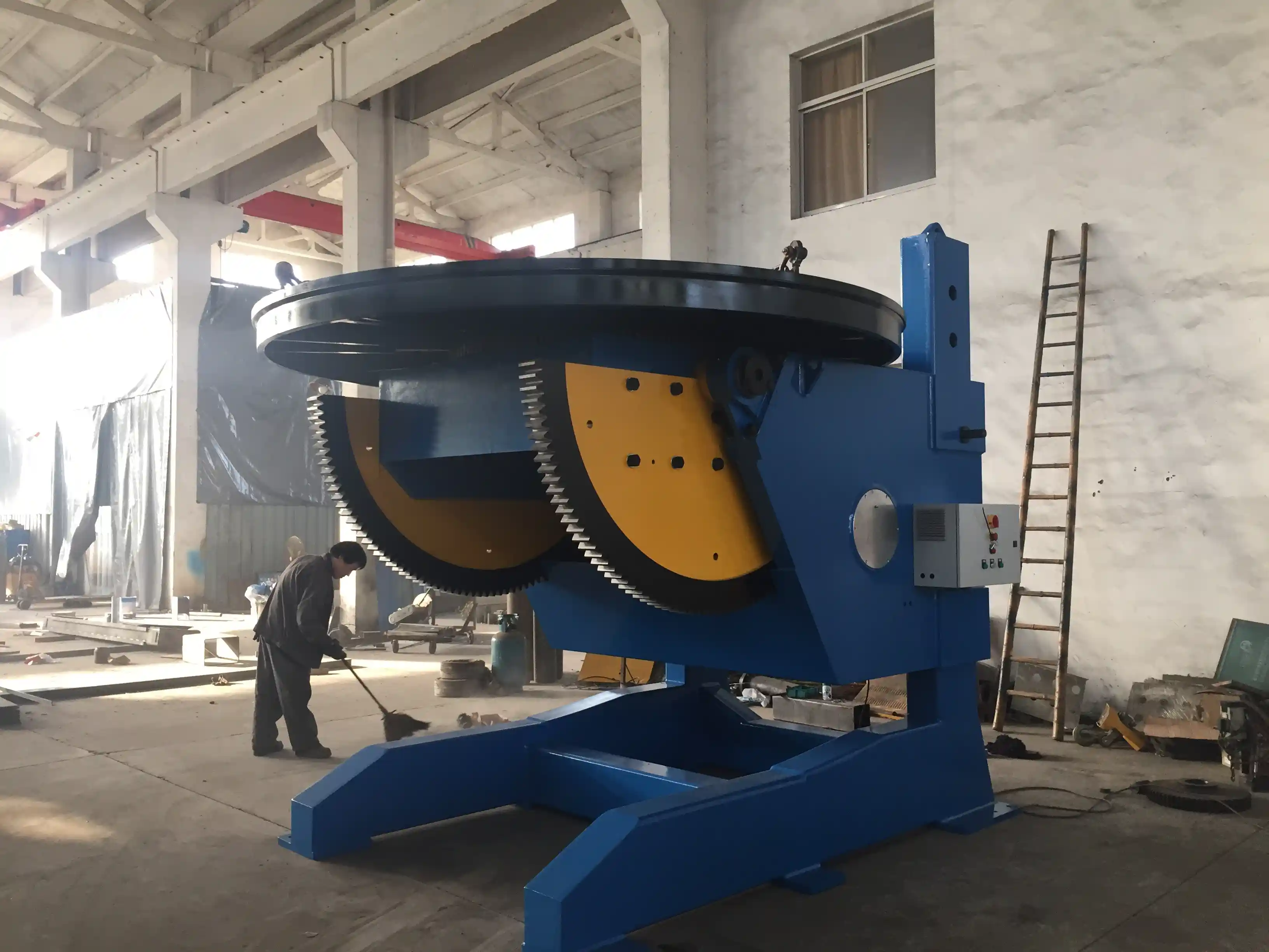
Precision-cut plate is easier to fit up and tack weld, but fit-up accuracy also depends on how the assembly is supported and rotated. <Innovative Applications of 10-Ton CNC Welding Rotators in Pressure Vessel Manufacturing> covers how CNC-positioned rotation reduces fit-up rework in heavy vessel fabrication.
Once the parts are cut to tolerance, welding sequence and positioning determine final straightness. <Tired of Complex Welding Challenges? How a 3-Axis Positioner Can Boost Productivity by 70%> covers how three-axis positioning improves weld access for complex structural components.
Long beams and heavy profiles create a separate handling bottleneck after cutting. <The Core Pillar of Heavy Manufacturing: The Outstanding Performance of Roller Stands in Key Processes> covers how roller stand layout stabilizes heavy sections during fabrication.
Supplier Evaluation and Investment Planning
Because a CNC cutting machine carries a long service life, supplier selection should be based on more than purchase price. A structured evaluation should include sample cutting, control system support, spare parts availability, local service response, and training. The supplier should be willing to test the same plate grades and thicknesses the shop actually uses, not only demonstration samples.
The machine should also fit the existing shop infrastructure. Power supply, compressed air or oxygen/fuel gas capacity, extraction ducting, floor loading, and lifting equipment all affect installation cost. A low purchase price can be quickly absorbed by site preparation if these utilities are not assessed early. For shops that need to meet customer quality audits, supplier documentation should align with the shop’s ISO 3834 or equivalent quality management requirements [5].
Investment planning should also account for consumables and service. Plasma electrodes, nozzles, swirl rings, flame cutting tips, oxygen and fuel gas, laser optics, and water jet abrasive are continuous costs. The most productive machine in a test environment may not be the most economical on the production floor if consumable life, duty cycle, and maintenance access are poor. A total-cost comparison over three to five years of expected production is usually more reliable than comparing initial quotations alone.
Specify a CNC Cutting System for Your Steel Structure Shop
A practical specification avoids vague requests such as “CNC cutting machine for steel structure” and instead defines the inputs the manufacturer needs to size and configure the system correctly. The following inquiry list helps reduce quotation time and improves the quality of the technical response:
- Material grades: carbon steel, high-strength steel, stainless steel, aluminum, or mixed.
- Plate thickness range: minimum and maximum thickness for each material group.
- Typical plate sizes and maximum part length/width.
- Annual tonnage and number of production shifts.
- Weld preparation requirements: square edge, single bevel, double bevel, K-bevel, or J-bevel.
- Existing CAD/CAM and nesting software.
- Power supply, gas supply, crane capacity, and extraction limitations.
- Required execution class, welding standard, and customer quality audit requirements.
WUXI ABK MACHINERY CO., LTD supports steel structure fabricators with CNC cutting and welding automation equipment selection, trial cutting, system integration, and after-sales support. For a technical discussion with no obligation, contact Zhang Jian at jay@weldc.com, call +86-510-83555592, or reach the mobile line at +86-13815101750.
Frequently Asked Questions
What is the most economical CNC cutting process for structural steel plate?
The answer depends on thickness and part geometry. For carbon steel in the 3–50 mm range, CNC plasma cutting usually offers the best balance between speed, edge quality, and consumable cost. For plate above roughly 50 mm, CNC flame cutting is often more economical and produces stable edge quality. Laser cutting is most economical for thin-gauge parts where high cutting speed and tight dimensional control reduce downstream work.
What cut quality tolerance should a steel fabricator require?
The tolerance should be linked to a recognized standard rather than a general description. ISO 9013 defines quality classes for perpendicularity, surface roughness, profile deviation, and edge rounding [1]. The project specification or welding standard then determines which class is acceptable. For structural work, the cut quality should also be compatible with the fit-up tolerances in AWS D1.1 or EN 1090-2.
Can CNC cutting machines produce weld bevels?
Yes. CNC plasma and flame cutting machines can produce square, bevel, K, and double-bevel edges in the same program cycle. The bevel angle and root face must be controlled as part of the welding procedure. A dedicated bevel head or a machine with three-axis torch control improves repeatability on long bevels.
How does CNC cutting improve structural steel dimensional accuracy?
CNC cutting removes manual layout and hand-torch variation by applying programmed geometry, kerf compensation, and consistent torch path control. It also allows repeated parts to be produced from the same verified program. The accuracy benefit carries into fit-up only if the machine is maintained, the plate is level, and the parts are handled without distortion.
What maintenance prevents cut quality drift?
Routine checks should include torch alignment, nozzle or tip condition, drive rack and rail cleanliness, gas flow, and nesting software updates. The machine should also be checked against a reference cut part at a defined interval. Most cut-quality drift is caused by worn consumables, misaligned torch height control, or dirty rails rather than control system failure.
References
[1] ISO 9013:2017, Thermal cutting — Classification of thermal cuts — Geometry product specification and quality tolerances.
[2] EN 1090-2:2018, Execution of steel structures and aluminium structures — Part 2: Technical requirements for steel structures.
[3] AWS D1.1/D1.1M:2020, Structural Welding Code — Steel.
[4] ISO 5817:2014, Welding — Fusion-welded joints in steel, nickel, titanium and their alloys (beam welding excluded) — Quality levels for imperfections.
[5] ISO 3834-2:2021, Quality requirements for fusion welding of metallic materials — Part 2: Comprehensive quality requirements.
If you’re interested, check out these related articles:
Low Efficiency in Pipeline Group Welding: How Intelligent Roller Racks Increase Productivity by 50%
Welding Rotator Precision Automation for Industrial Fabrication: Expert FAQ Guide
Wind Tower Welding Challenges: How Advanced Hydraulic Lifting Systems Boost Production by 40%
Exceptional Application Value: How Fixed-Height Welding Positioners Drive Advancements in Offshore and Shipbuilding Manufacturing
Revolutionary Solution for Pressure Vessel Welding: Technical Analysis of 360-Degree Rotating Welding Positioners
 English
  Español
  Français
  Deutsch
  Português
  Русский