
Membrane panel welding parameters cannot be pulled from a single chart and applied to every panel line. Voltage, current, and travel speed interact with tube diameter, wall thickness, fin bar width, fit-up gap, wire diameter, and shielding gas. When one value moves, the others must move with it, or the result is burn-through on a thin bar, incomplete fusion at the tube root, or straightness loss across a long water wall panel. I have spent more than twenty years working with welding equipment for boiler panel production, and the first parameter check I make is not the voltage dial; it is the joint condition.
Considering Material, Fit-Up, and Distortion Before Setting Membrane Panel Welding Parameters
Welding parameters are the final act in a chain of preparation decisions. Before voltage and current are set, I look at tube diameter, wall thickness, bar width, and the fit-up between tube and bar. If the gap is uneven, no parameter will produce a stable side by side pass on both edges of the bar. A common failure is setting a high current to compensate for poor fit-up. That widens the weld pool and increases heat input, which then pulls the panel out of flatness. For carbon steel water wall panels, the joint should be tight enough that the arc can bridge the gap without exposing the tube root. Fit-up beyond 0.5 mm usually requires a mechanical correction before welding, not a parameter correction.
Panel length changes the balancing act. A 12 meter panel stores distortion energy differently than a 2 meter test coupon. When one side of the panel is welded and the other side is still bare, longitudinal shrinkage can bow the assembly. The parameter sheet should therefore include a weld sequence, not only a voltage and current range.
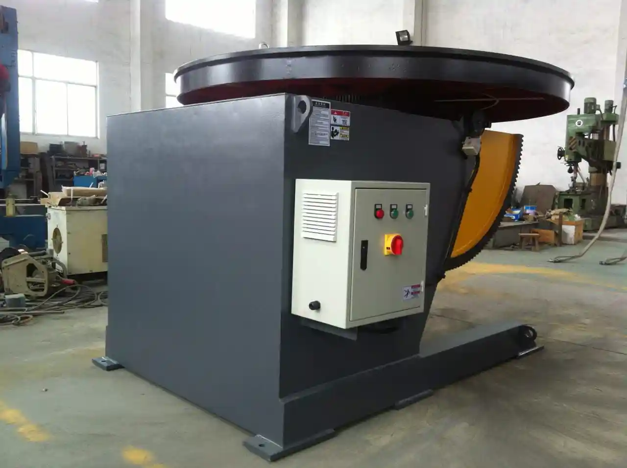
Long panel alignment before welding decides how much local adjustment the arc must correct. <How to Improve the Quality of Pipe Welding Through a High-Precision Welding Positioner> covers why repeatable positioning and consistent joint presentation improve pass to pass consistency on long cylindrical and panel type work.
Setting Voltage and Current for Consistent Membrane Panel Penetration
Current largely controls penetration into the tube and bar. Voltage controls the arc length and bead profile. In membrane panel work I treat these as a pair because changing one usually changes the heat input equation. A shallow, crowned fillet on a membrane bar usually means voltage is too low for the current. A wide, washed out bead with undercut along the bar edge means voltage is too high or travel speed is too slow.
The table below lists single wire GMAW starting ranges for carbon steel membrane panels using ER70S-6 wire and a short stickout.
| Bar thickness | Tube wall | Wire diameter | Starting current | Starting voltage | Travel speed |
|---|---|---|---|---|---|
| 4 mm | 3 to 4 mm | 1.2 mm | 200 to 230 A | 24 to 26 V | 400 to 550 mm/min |
| 5 mm | 4 to 5 mm | 1.2 mm | 220 to 250 A | 25 to 27 V | 350 to 500 mm/min |
| 6 mm | 5 to 6 mm | 1.2 mm | 240 to 280 A | 26 to 28 V | 300 to 450 mm/min |
These values assume good fit-up and a flat panel position. If the fit-up has gaps, I do not raise current first. I tighten the assembly or use a short bridge pass at the root before running the final fillet. Shielding gas is part of the parameter set. A mixed gas with 15 to 20 percent CO2 produces a stable spray arc at the higher end of these ranges; pure CO2 is cheaper but changes the voltage window and spatter pattern. If the shop changes gas supplier, the parameters must be requalified.
Matching Travel Speed to Membrane Bar Thickness and Fit-Up
Travel speed is the parameter that most directly controls heat input. In a long panel, a small reduction in travel speed may not look different on a 300 mm coupon, but across 12 meters it changes total heat input and distortion. I prefer to set travel speed by measuring the weld toe transition into the tube and the bar. If the toe is sharp, the pass is too cold or too fast. If the toe rolls over and the bar edges are washed out, the pass is too hot or too slow. For 4 to 5 mm bar, I hold the higher end of the travel speed range and check the back side for discoloration. For 6 to 8 mm bar, I slow the pass enough to get a full tie-in at the bar edge. Fit-up gap matters here: a 0.4 mm gap and a 0.8 mm gap can require different travel speeds even when the base metal thickness is the same.
If tube wall thickness is below 4 mm, travel speed should not be set without checking tube wall penetration. A hot, slow pass can melt into the tube in a way that is hard to see on the outside. If the tube is pressure bearing, that hidden root penetration becomes a wall thickness problem.
Heat input control only works when the panel stays in a fixed position instead of drifting under the torch. <Mastering Heavy Manufacturing: How Climbing Roller Stands Become the Cornerstone of Efficient Welding> covers how stable roller support keeps long workpieces aligned during heavy multipass welding.
If your program involves mixed tube diameters or bar widths on the same panel line, it is worth confirming heat input and travel speed against a prequalified window before ordering fixturing. Share your tube and bar dimensions with jay@weldmc.com and we can check the parameter range against the machine configuration.
Verifying Membrane Panel Welding Parameters Before Production
Before a full shift, weld a 1 to 2 meter sample using production gas, production wire, and production fixture. Cut three sections at the start, middle, and end of the run. Check leg length, throat depth, fusion at the root, porosity, undercut, and panel width after welding. A macro etch on one section is more useful than a visual check alone because it shows whether the weld actually tied into the tube and bar. If the sample passes, lock the settings. If it fails, change only one variable at a time.
Parameter lock should include wire feed speed, trim or pulse settings, stickout, torch angle, gas flow, travel speed, current, voltage, preheat, and clamping position. On a dedicated Membrane Welding Machine, saving a qualified parameter set reduces setup variation between shifts. Operators still need a written record because the display values may not show wire stickout or gas flow.
Building a Production Parameter Window Without Guessing
Most membrane panel welding failures I have seen were not caused by a single bad number on the screen. They came from a parameter set copied from another shop, then used with different gas, fit-up, or material. If your line is already making panels, record every variable for one full shift before changing anything. If you are setting up a new boiler panel production line, the next step is to define the parameter window before you buy or modify fixturing. Send your tube diameter, wall thickness, bar width, material grade, wire diameter, and target output to jay@weldmc.com, or call Wuxi ABK at +86-510-83555592. We can work through the starting parameters and machine configuration with you so the first production run is based on a tested window, not guesswork.
Clarifying Membrane Panel Welding Parameters Through Common Questions
Does Travel Speed Matter More Than Voltage When Panels Start Bowing?
Yes. Travel speed is usually my first adjustment when a panel bows after welding because it changes heat input more predictably than voltage alone. If both sides of a panel receive the same current but one side is welded faster than the other, the slower side shrinks more and pulls the panel into a curve. I slow or speed up the pass only after checking fit-up and clamping, then recheck flatness over the full length. On long water wall panels, a modest speed difference between edges can show up as twist or crown over 12 meters. Record the speed change and cut a cross-section before returning to production.
Does Higher Voltage Always Mean Deeper Penetration Into the Tube?
No. A common mistake is to think that raising voltage alone increases penetration. In GMAW, penetration is tied more to current and wire feed speed. Voltage mainly changes the arc length and bead width. A high voltage with low current will produce a wide washy weld with shallow root fusion, especially on a thin fin bar. If the weld needs more root tie-in, increase the current or reduce travel speed, then adjust voltage only to restore the proper bead profile. Before changing either value, check the wire stickout. A longer stickout reduces the actual current even if the display setting has not changed.
What Current Range Works for 4 to 6 mm Membrane Bars?
It depends on the bar thickness, wire diameter, and whether the line uses single wire GMAW or a twin wire submerged arc process. For single wire GMAW with 1.2 mm ER70S-6 on 4 mm bar, a starting range around 200 to 230 A with 24 to 26 V often works. A 6 mm bar may require 240 to 280 A with 26 to 28 V, and twin wire submerged arc welding runs higher current but splits the heat between two arcs. These are starting ranges, not universal settings. The final window must be confirmed by sectioning a production length sample and checking leg size, throat depth, and root fusion.
Why Do Parameters That Worked on a Sample Fail on the Full Panel?
In panel line projects I have supported, the most common reason is that the sample did not use production conditions. The shop qualified a short coupon on clean material, then production ran with older wire, a different gas mix, or more fit-up variation. A 2 meter sample also does not show cumulative distortion the way a 12 meter panel does. Wire stickout changes when the torch angle shifts along the panel, and that changes true current. Before changing the stored parameters, I compare the production setup against the sample record: wire lot, gas flow, stickout, fit-up, clamping, and travel speed. Share your panel drawing, tube size, and bar thickness with jay@weldmc.com and we can check which starting parameters fit your production.
If you’re interested, check out these related articles:
Low Efficiency in Pipeline Group Welding: How Intelligent Roller Racks Increase Productivity by 50%
Excessive Misalignment in Pipeline Welding: Wuxi ABK Welding Turntable Precision Positioning Solution
Welding Manipulators for Wind Tower Fabrication: Revolutionizing Production Efficiency
 English
  Español
  Français
  Deutsch
  Português
  Русский