Producing a pressure vessel that weighs over 500 tons and stretches more than 60 meters in length requires an entirely different approach to fabrication. The equipment that comfortably handles a 10-ton vessel becomes a bottleneck when shells reach 6 meters in diameter and wall thicknesses exceed 150 mm. We have been engineering heavy welding automation systems for more than two decades, and the single most frequent mistake we see in new projects is underestimating the supporting infrastructure. The welding machine itself is rarely the constraint. The rotators, positioners, and material handling systems that keep a 200-ton workpiece stable and accessible during every weld pass are what determine whether a project meets both delivery deadlines and ASME code requirements. This article explains the essential equipment and production methods for massive pressure vessel fabrication, from plate preparation to final inspection, with an emphasis on the handling systems that make extreme-size manufacturing possible.
How Massive Vessel Dimensions Shape Equipment Selection
Everything about a massive pressure vessel production line follows from three numbers: shell diameter, maximum section weight, and wall thickness. When a vessel exceeds 4 meters in diameter, conventional fixed-height welding rotators no longer provide adequate access. We have supplied production lines where vessels reached 6.5 meters in diameter, requiring hydraulic elevation adjustment on every rotator set just to keep the welding head within the optimal working envelope. The rotators also need load capacities substantially above the workpiece weight. A vessel barrel weighing 80 tons should ideally run on rotators rated for 100 tons or more. The additional capacity provides margin for dynamic loading during rotation, especially during submerged arc welding (SAW) where slag can momentarily bind the contact zone. At WUXI ABK, our standard adjustable-height rotators are built with self-aligning ZG45 cast steel rollers, and we specify 1.25 times the static load for continuous-duty applications.
Thick-wall vessels introduce another constraint: heat input control. A 150 mm wall thickness demands welding procedures with carefully managed interpass temperatures, and that means the positioning equipment must index precisely and repeatedly. A positioner with 1 degree of backlash translates to several millimeters of arc wander at a 3-meter radius, which is unacceptable for the root pass of a longitudinal seam. We use servo-driven rotation with absolute encoders on positioning equipment above 3 tons, achieving 0.02 mm repeatability, specifically because pressure vessel shops cannot afford rework on a 100-ton component.
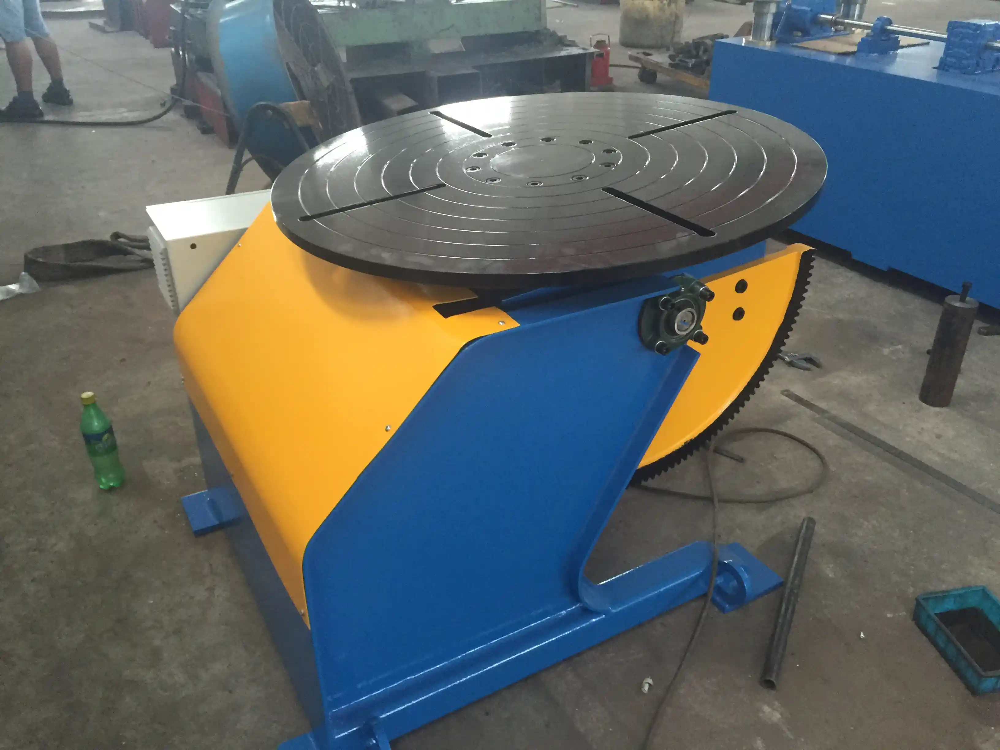
Plate Preparation and Rolling for Thick-Wall Shells
Before any welding begins, plate preparation sets the baseline for dimensional accuracy. Plates for massive vessels typically arrive in widths up to 4.5 meters and lengths exceeding 12 meters. The edge preparation must be machined rather than flame-cut for thicknesses above 80 mm to avoid the heat-affected zone cracking that oxy-fuel cutting can introduce in high-carbon steels. We have seen shops try to save time by flame-cutting the weld bevels, only to find micro-cracks during magnetic particle inspection days later. A precision bevel, whether U-groove or compound J-groove, pays back during welding because it reduces the filler metal volume and therefore the cumulative distortion.
Rolling these plates into shells is the first major handling challenge. A plate that starts as a flat 100-ton slab of SA-516 Grade 70 steel must be formed into a near-perfect cylinder within a few millimeters of roundness. The plate bending machines for this work are often custom-ordered with extended roll lengths and heavy-duty drives. More importantly, the shell must be supported immediately after rolling to prevent sag. We usually recommend a set of powered fit-up rotators at the rolling station so that the shell can be transferred and rotated without exposing the thin-walled profile to bending stress. For diameters above 5 meters, we integrate alignment carriages with laser guidance to confirm the longitudinal seam edges are within 0.5 mm parallelism before tack welding.
The fit-up stage is where many projects lose schedule. Aligning two massive shells for a girth weld requires either overhead cranes with fine-positioning capability or dedicated fit-up rotators with hydraulic lateral adjustment. We build fit-up systems that combine roller support with independent side-shift control on each carriage, which allows a single operator to align shell edges without the trial-and-error of crane signals. This alone can cut two hours from each girth joint.
Welding Equipment for Longitudinal and Circumferential Seams
The welding methods for massive pressure vessels are well established: submerged arc welding for longitudinal seams and circumferential seams, with flux-cored arc welding or gas metal arc welding for root passes where accessibility is limited. What changes with scale is the operating envelope that the welding equipment must cover. A column and boom manipulator for a 60-ton vessel might need a 6-meter horizontal reach and 5-meter vertical stroke. For a 400-ton reactor shell, the manipulator column may need to be gantry-mounted with a horizontal travel of 12 meters and a vertical reach of 8 meters or more.
Our experience is that shops often under-spec the manipulator’s boom stiffness. At extended reach, a boom that sags by 2 millimeters creates a torch angle error that can produce undercut or inconsistent penetration across the weld face. We use box-beam structures with internal ribbing and linear guideways rated for that deflection limit, and we rigidly mount the manipulator bases to embedded rails. The column rotation function, which allows the boom to swing to either side of the vessel, becomes essential when multiple vessels are staged in the same production bay. A 360-degree continuous rotation column, available on our larger models, eliminates the need to reposition the entire machine between workpieces.
For the girth welds themselves, the vessel is rotated while the welding head remains stationary. This is where the combination of a welding rotator set and an automated SAW tractor or manipulator-mounted head is standard. The rotators must provide smooth, stepless speed control between 100 mm/min and 1000 mm/min at the weld surface; any variation in rotation speed changes the weld metal deposition rate. We use frequency-converted drives with encoder feedback to maintain speed within 2% of the setpoint, even as the load changes due to slag shedding. If you are welding SA-387 chrome-moly steel, the preheat requirement (often 200°C or higher) demands rotators with thermal protection for the bearings and motors. We have built units with heat shields and remote grease lines for exactly that application.
Heavy-Duty Positioners for Nozzle and Attachment Welding
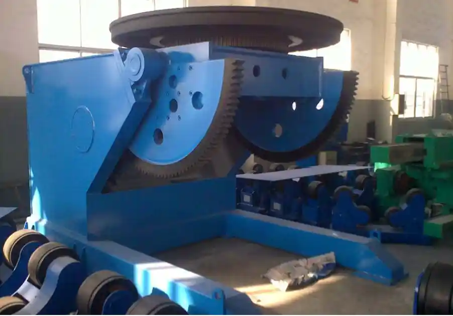
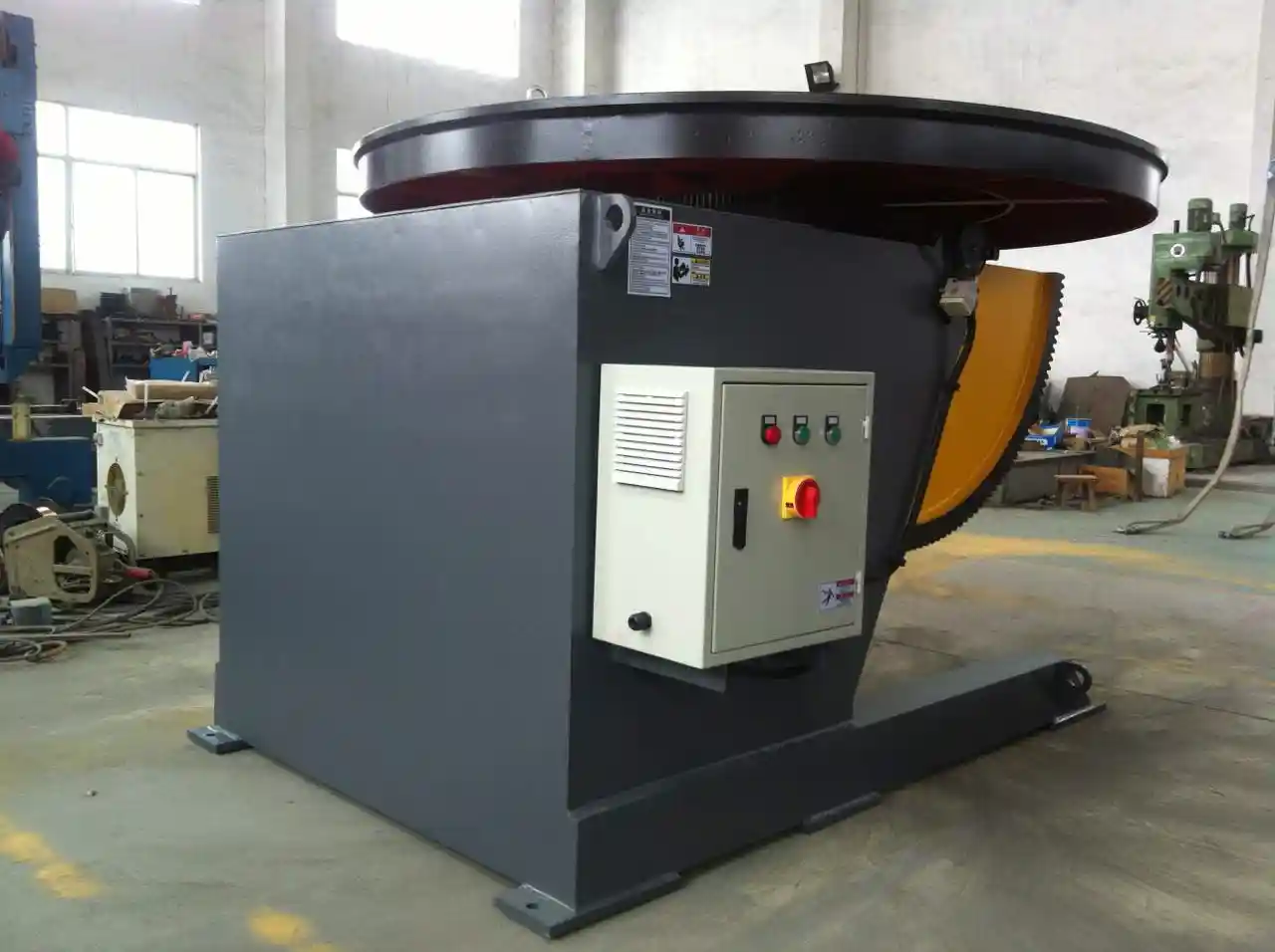
The body of a massive pressure vessel may be cylindrical, but the fabrication complexity lies in the nozzle openings, support saddles, lifting lugs, and internal trays. Each of these features requires the vessel section to be held in an orientation that gives the welder flat-position access. Conventional head-and-tail positioners up to 5 tons are insufficient for a 150-ton vessel head with a 2-meter manway flange. You need a self-standing positioner with a load capacity that matches the heaviest component you will rotate, not the average.
We manufacture adjustable-height positioners with capacities from 5 tons to 100 tons. The 100-ton positioner uses a worktable diameter of 1800 mm with hydraulic lifting, and it can rotate the workpiece 360 degrees continuously. What matters is not just the lifting force but the overturning moment capacity. A vessel head with a nozzle offset by 1.5 meters from the center of rotation generates a substantial bending moment. Our positioners are rated for eccentric loading as well as pure vertical load, and we recommend that shops calculate the overturning moment at 90-degree tilt before selecting a positioner model. A 30-ton head with a 1.2-meter eccentricity requires a positioner with an overturning moment rating of at least 36 ton-meters, which typically pushes you into the higher-capacity frame.
For in-place nozzle welding on the assembled vessel shell, the positioner is often used in combination with a column and boom manipulator. The vessel is rotated to bring each nozzle location to the top position, the manipulator head is positioned over the opening, and the weld is deposited with the torch oriented vertically. This setup requires that the positioner rotation and the manipulator head position be coordinated. We provide PLC interfaces that allow the positioner to index to preset angles so that the welding program can call up each nozzle station automatically.
Quality Compliance and the Equipment That Delivers It
ASME Section VIII Division 1 and Division 2 specify the design and fabrication rules for pressure vessels, but they do not specify what equipment you must use. However, the required inspection results effectively drive the equipment specification. Radiographic testing of full-penetration welds on thick sections demands a consistent weld profile free of internal flaws. Achieving that profile on a 200 mm thick longitudinal seam requires that the SAW head maintain the exact standoff distance and travel speed for the full weld length, often 8 meters or more. A manipulator with a rigid boom and precise vertical tracking, plus a rotator that does not slip under load, is necessary to meet the RT acceptance criteria without repeated repairs.
Post-weld heat treatment (PWHT) adds another dimension to equipment planning. A vessel that must be stress-relieved at 620°C for several hours will expand significantly. The supporting cradles and rotator rollers must accommodate the thermal growth without restraining the shell. We specify roller assemblies with side float and axial compliance on rotators destined for vessels that will be roller-heated in place. Ignoring this detail leads to distorted shells and cracked attachment welds after PWHT. We have been called to retrofit rotators after a shop damaged a completed vessel during the cool-down phase because the fixed rollers constrained the shell contraction.
The inspection equipment itself often requires special access provisions. Automated ultrasonic testing (AUT) crawlers need a clean track along the weld, and the vessel must be rotated at a controlled speed to match the scanner speed. The rotator control system must therefore accept an external speed command from the AUT system, not just a local pendant. We pre-wire our rotators with analog input interfaces so that NDT contractors can plug in directly.
Production Line Layout for Massive Vessel Fabrication
A complete production line for massive pressure vessels is a linear or U-shaped flow from plate storage to final inspection. The layout must account for the fact that each station is occupied for days or weeks, not hours. At the front end, plate preparation (blasting, cutting, edge machining) requires an infeed system that can handle single plates weighing 50 tons or more. Magnetic plate handling systems or heavy-duty roller conveyors are common.
The rolling and fit-up station follows, then longitudinal seam welding, then girth welding as sections are added. Between these stations, the vessels must be transported without distortion. A tracked transfer car with a weight capacity equal to the gross vessel weight is the standard. We have designed tracks that serve multiple parallel bays so that vessels can be side-shifted when one welding station is occupied, preventing bottlenecks.
The final assembly bay, where all shell sections are welded together and nozzles are added, needs the highest crane capacity. It also needs the highest-power manipulators and the strongest rotators. Typically, one set of adjustable-height rotators is dedicated to the final girth welding, and a large three-axis positioner handles the head sections. The end CTA section should be near here but we’ll place it correctly after the FAQ.
When Scale Demands More Than Standard Equipment
As pressure vessel size continues to grow, driven by larger refinery reactors, ammonia converters, and nuclear components, the equipment industry has had to push beyond what was considered heavy fabrication a decade ago. A 10,000-ton reactor vessel cannot be fabricated in a single piece because no crane can lift it. It is built in sections, shipped, and assembled on site. The shop equipment still needs to handle the maximum section weight, which may be 600 tons or more. That requires rotators with 300-ton capacity per pair, positioners capable of rotating a 200-ton head, and manipulators with booms reaching 14 meters. We are currently delivering equipment of this scale, and the engineering challenge is not just making it bigger but keeping it precise under such extreme loads. The base frames, the gear reducers, and the safety interlocks all require a step change in design philosophy, moving from industrial machinery to heavy civil engineering standards.
If your next project involves a pressure vessel beyond the capacity of your current shop equipment, we recommend starting the equipment specification process 12 to 18 months before you need to begin fabrication. The lead time for a fully customized 100-ton positioner or a 300-ton rotator set is typically 6 to 8 months, not including civil works. With your vessel drawings and production schedule in hand, we can verify that the proposed equipment configuration meets the section weights, diameters, and cycle times you need. Share your part numbers, vessel dimensions, and target daily production rate with jay@weldc.com or call +86-510-83555592, and we will match the detailed technical data we have gathered from previous large-vessel projects to your manufacturing plan.
Common Questions About Heavy Pressure Vessel Fabrication
What is the largest pressure vessel that can be shop-fabricated?
The upper limit is set by the lifting capacity of the overhead crane, which in most heavy fabrication shops is between 250 and 500 tons. Shell sections for an 8-meter diameter vessel can weigh up to 200 tons each, so a 500-ton crane allows assembling several sections in the shop. Beyond that, the vessel is built in rings that are shipped separately and welded together at the installation site. We have seen an increasing trend toward split-shop/site welding for petrochemical reactors, and the site welding equipment requires portable SAW systems and modular rotators that can be assembled on a temporary foundation.
How do you maintain shell roundness during multi-pass welding?
Roundness is controlled by a combination of internal bracing and the roller pitch on the welding rotators. For vessels above 5 meters in diameter, we recommend a minimum of three roller stations per shell section, with the outer two providing the main support and the middle one acting as a stabilizer. Internal spider braces, usually adjustable, are placed every 3 meters along the shell to resist the ovalization caused by the heat of each weld pass. After welding, the brace tension is released gradually while the shell is rotated; any residual out-of-roundness is corrected by spot heating.
Can a single manipulador de soldadura handle all the seams on a massive vessel?
Not in an efficient production layout. A dedicated longitudinal seam manipulator is often installed at the fit-up station, a separate girth welding manipulator serves the assembly bay, and a smaller manipulator handles nozzle attachments. Trying to share one manipulator across all operations creates a bottleneck because the setup time between tasks is too high. In our turnkey line designs, we typically configure three manipulators of different sizes, each stationed at its permanent task.
How do you prevent the rotator rollers from damaging the vessel surface?
For carbon steel vessels, the roller surface hardness should be lower than the vessel shell to prevent indentation. We use ZG45 cast steel rollers with a hardness of HRC 55-60, which is compatible with most pressure vessel steels. For stainless steel cladding, polyurethane roller covers protect the surface finish. The real risk is not the roller material but the contact stress at the roller-shell interface. By keeping the roller diameter large relative to the shell diameter and ensuring the full roller width contacts the shell, the Hertzian contact stress stays below the yield point of the shell material.
What are the lead time considerations for a complete massive vessel production line?
A full line, from plate handling through final NDT, typically takes 10 to 14 months from order to commissioning. The longest-lead items are the heavy positioners (6-8 months), the gantry-mounted manipulators (5-7 months), and the custom-fit transfer cars (4-6 months). If you have an active vessel contract with a delivery deadline, we recommend issuing the equipment purchase order as soon as the vessel design is sufficiently frozen to confirm shell section weights, because equipment lead time often determines the overall project schedule, not the fabrication hours. Share your timeline and vessel weight data with us at jay@weldc.com, and we will map out a realistic delivery plan that aligns your equipment commissioning with your first shell rolling date.
Se estiver interessado, consulte estes artigos relacionados:
O pilar central da produção pesada: O excelente desempenho dos suportes de rolos nos principais processos
Rotadores de tubos e rolos de torneamento: Equipamento essencial para o fabrico moderno de condutas
 English
  Español
  Français
  Deutsch
  Português
  Русский