When a pressure vessel fabricator needs to weld a manifold with a 40‑degree tilt on a 12‑ton assembly, the catalog page for a standard welding positioner is of little use. Standard positioners handle straightforward cylindrical sections well, but real heavy fabrication often calls for custom welding positioner designs that accommodate unusual tilting angles, asymmetric load distributions, and extreme weight. As a welding automation engineer with more than twenty years in equipment design and system integration, I have seen how these special requirements demand more than a higher load rating. They demand a focused engineering approach from the first specification through final validation.
Limitations of Standard Welding Positioners
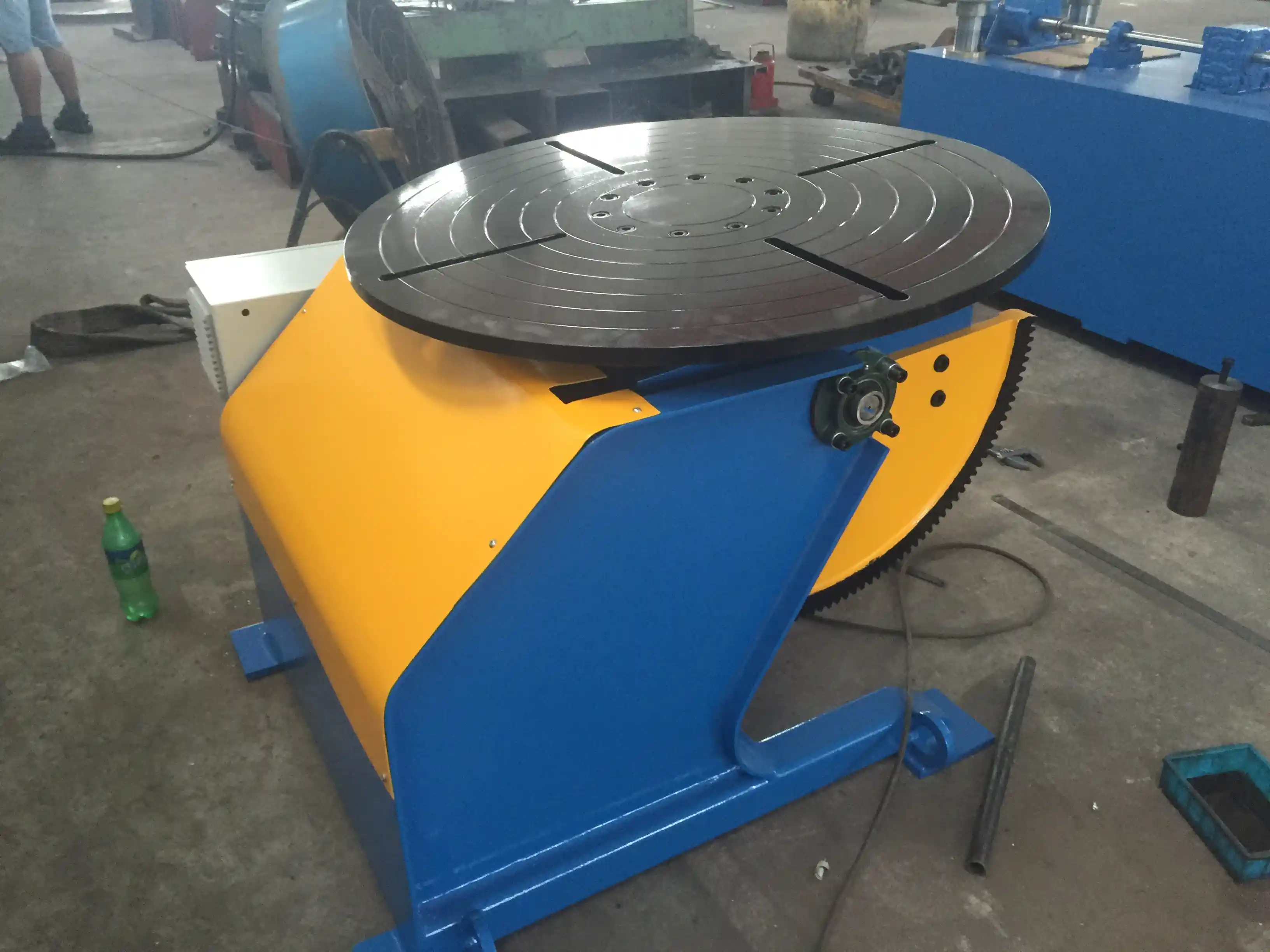
Off‑the‑shelf welding positioners are designed around common workpiece geometries: cylindrical vessels, pipes, and frames with symmetrical weight distribution. A standard 1‑ton fixed‑height positioner such as the ABK HBJ‑10 can manage a maximum eccentric distance of 150 mm and a center‑of‑gravity offset up to 200 mm. Many heavy fabrications, however — excavator booms, wind turbine flanges, pressure vessel nozzles — have centers of gravity far beyond those limits, or they require tilting angles outside the typical 0‑90° range.
When the workpiece is asymmetrical, the positioner table experiences an overturning moment that standard worm‑gear drives simply were not sized to handle. Using an undersized unit leads to positioning drift, weld defects, and a serious safety risk. The first sign that a custom design is necessary arrives when the eccentric load exceeds the published limit or the required tilt angle is unavailable in any catalog model.
Special Tilting Angle Requirements
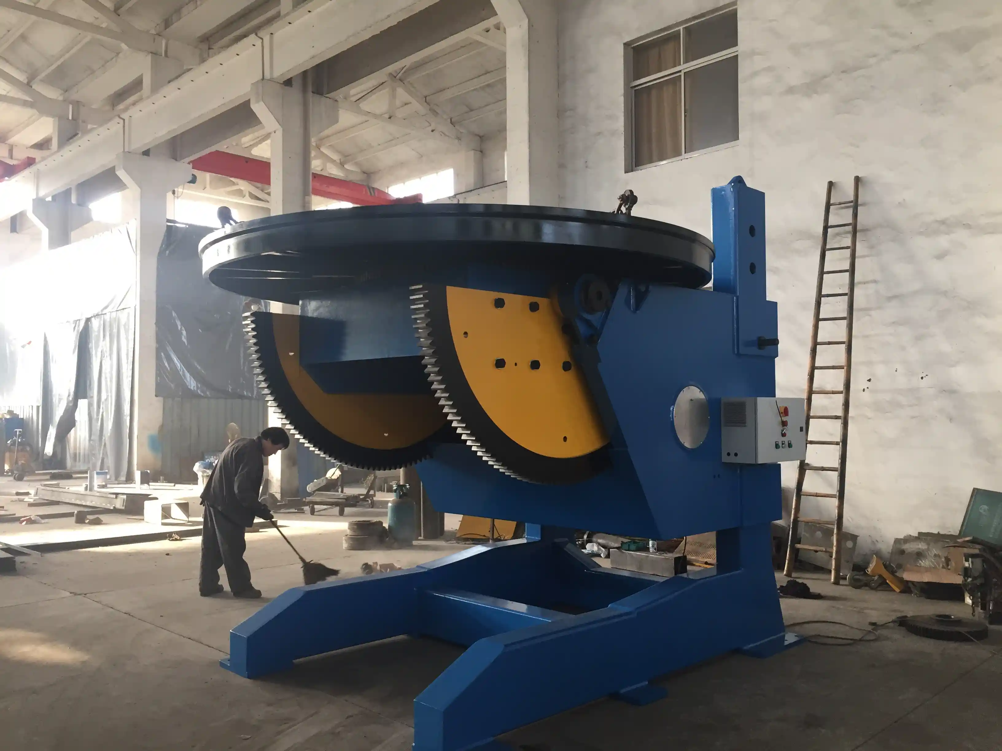
Many pressure vessel and structural welding procedures call for tilting angles between 0° and 135° to position seams for flat or horizontal welding. Standard fixed‑height positioners generally top out at 90° or 120° turn over. To achieve 135° tilt, a cycloidal‑worm dual‑stage reducer is often combined with an L‑type frame, as seen in ABK’s LHBJ series. For applications that demand frequent angle changes under heavy load, hydraulic tilting with proportional control offers a smooth, powerful alternative.
The table below compares standard and custom tilt capabilities for reference.
| Positioner Configuration | Standard Tilt Range | Extended Custom Range | Aplicação típica |
|---|---|---|---|
| Fixed‑height single‑axis | 0‑90° | 0‑135° with special reducer | Pressure vessel seams |
| L‑type with turnover | 0‑120° | 0‑135° hydraulic | Heavy structural box sections |
| Adjustable height L‑type | 0‑120° | 0‑135° plus 500 mm elevation | Wind tower flanges |
| 3‑axis precision | 0‑90° tilt, ±180° rotation | 0‑135° tilt, 360° continuous | Células de soldadura robotizadas |
Load and Overturning Moment Dynamics
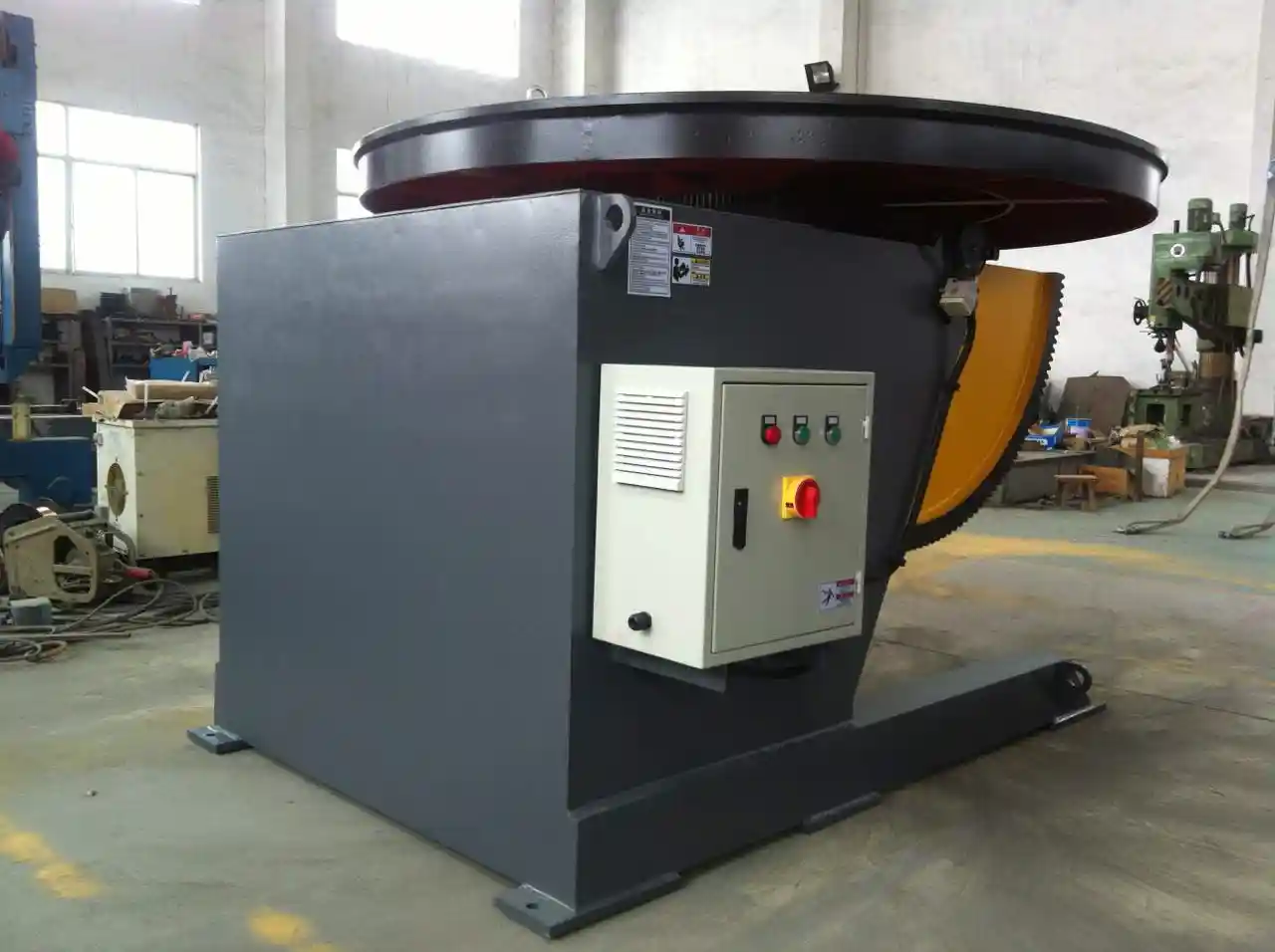
A 5‑ton load capacity rating does not mean the positioner will safely manage a 5‑ton workpiece with its center of gravity 500 mm off the table. The real limiting factor is the overturning moment, calculated as the product of the load and the eccentric distance. For the ABK HBJ‑50 5‑ton positioner, the maximum center‑of‑gravity distance is specified at 300 mm; a load at 600 mm would generate double the moment and could deform the slewing bearing or the base structure.
Custom welding positioner designs start with a load analysis that maps the workpiece’s mass distribution across the full tilt envelope. Engineers then size the slewing bearing and base frame accordingly. In projects I have supported, we reinforced the L‑support arm with additional gussets and upgraded to a larger‑diameter slewing bearing to handle extreme eccentricity. When the overturning moment exceeds a standard model’s capacity, we often add a counterweight or widen the base footprint, though these changes increase floor space and cost. The key is to supply accurate part dimensions and weight data early; then the exact moment can be calculated and the positioner designed to maintain ±0.5° accuracy throughout the tilt cycle.
Key Customization Features
Beyond load and tilt, several design features separate a robust custom positioner from a standard unit.
- Adjustable height, either hydraulic (up to 2000 mm elevation) or manual, to match the welding manipulator’s boom and keep the arc in the optimal position.
- Worktable diameter extension and additional T‑slots for complex fixturing. For large flanges, a 1500 mm or even 3000 mm table is required.
- Drive system upgrades: servo motors with planetary reducers replace AC motors when positional accuracy tighter than ±0.1 mm is needed.
- Water‑cooled tables and explosion‑proof certifications for petrochemical or hazardous environments.
- Siemens PLC control with more than 100 preset programs, making robotic integration straightforward.
Every customization adds lead time, but it also removes the compromises that limit weld quality. If your project involves a workpiece that is both heavy and highly asymmetric, the right combination of hydraulic tilt, adjustable height, and a reinforced L‑support can transform an impossible weld into a routine production task.
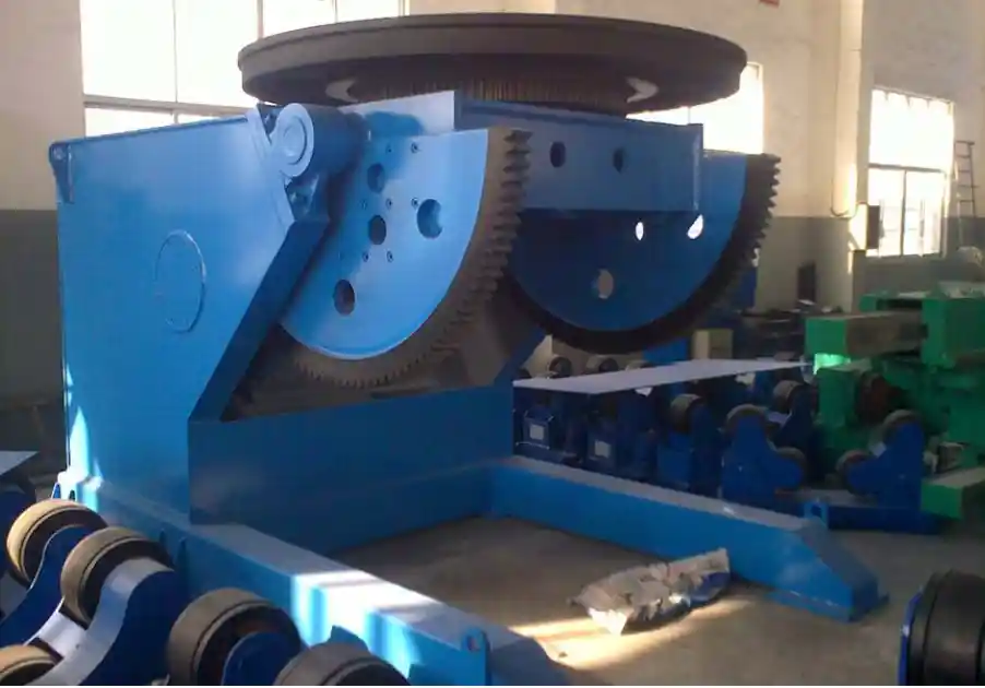
If your workpiece has an off‑center load beyond standard limits, the engineering analysis becomes critical. We can run a finite element load case and verify the L‑support design before quoting. Contact our team at jay@weldc.com with your part drawings and weight distribution for a no‑obligation feasibility review.
A Custom Welding Solution Built to Your Requirements
A custom welding positioner is not a commodity purchase; it is a collaborative engineering project. The most successful outcomes I have been part of began with a detailed specification discussion that included part geometry, weight distribution, and desired welding positions.
Send us your part drawings, the maximum weight, and the tilting angles you need to jay@weldc.com, or call +86‑510‑83555592. We will prepare a feasibility study and a custom positioner proposal backed by more than two decades of heavy fabrication positioning experience.
Common Questions About Custom Welding Positioner Projects
How long does a custom welding positioner take to design and manufacture?
The timeline depends on the scope of customization. A simple modification such as an extended L‑support and hydraulic tilt add‑on can typically be completed in 8 to 10 weeks. A fully custom multi‑axis positioner with robotic interface and specialized worktable may require 12 to 16 weeks. Early engineering involvement shortens the front‑end design phase and helps avoid later rework.
Can an existing standard positioner be modified for a special load?
Some upgrades are possible, such as adding counterweights or reinforcing the base frame. For eccentric loads beyond the design moment capacity, however, a new purpose‑built unit is the safer choice. Retrofitting rarely achieves the same structural integrity and can void certifications. When the overturning moment is the primary concern, a fresh design yields the most reliable solution.
Is a hydraulic tilting positioner more accurate than a mechanical gear type?
It depends on the load and duty cycle. Hydraulic tilting delivers high torque and smooth motion for very heavy pieces, but maintaining ±0.5° repeatability requires a proportional valve and closed‑loop control. A mechanical cycloidal or worm‑gear drive with a servo motor offers inherent stiffness and positional accuracy under variable loads, though it may be limited in maximum torque. For many custom builds we use a hybrid approach: servo‑driven rotation for precision and hydraulic tilt for force.
What if I need a positioner that handles both long pipe sections and large‑diameter flanges?
In projects we have supported, a dual‑purpose positioner required an adjustable‑height L‑support and a modular worktable with interchangeable fixture sets. The base frame is designed to accept multiple tooling configurations, so the same machine can switch between pipe welding and flange welding cycles with minimal changeover time. This approach reduces overall equipment investment when floor space is tight.
How do I ensure the custom positioner will integrate with my existing robotic cell?
Our positioners are engineered with standard interfaces for ABB, KUKA, FANUC, and Yaskawa robots, using Siemens PLCs with predefined communication macros. During the design phase we establish the protocol (EtherNet/IP, ProfiNet, etc.) and mechanical mounting points, and a factory acceptance test verifies full integration before shipping. Share your robotic cell specifications and our engineering team will prepare a detailed integration plan that fits your production setup.
Se estiver interessado, consulte estes artigos relacionados:
Problemas de soldadura de torres eólicas novamente: Como os rotadores inteligentes da linha de crescimento aumentam a produtividade por 50%
O espaço da oficina é demasiado pequeno? Como as lanças de coluna poupam espaço no chão da 50%, ao mesmo tempo que aumentam a segurança e a eficiência
Wuxi ABK Professional Welding Rotary Equipment: Precision Welding Solution for Pressure Vessel Manufacturing
 English
  Español
  Français
  Deutsch
  Português
  Русский