In heavy fabrication, work-in-progress does not come from slow welding. It comes from the space between machines. When a 5-ton column section sits on a pallet between cutting and positioning, that is WIP eating floor space and tying up cash. I have walked through too many shops where half the factory footprint is buffer inventory, not value-adding workstations. Lean manufacturing equipment configuration attacks this directly: by replacing standalone machines arranged by department with integrated production cells arranged by process flow, shops can cut WIP by 40% or more and reclaim the floor space that idle components occupy. The difference is not marginal. It changes how a shop operates day to day.
Where WIP and Footprint Actually Come From in Fabrication
Most fabrication shops are not laid out by process sequence. They are laid out by machine type. Cutting machines sit in one bay, welding positioners in another, and between them is a growing buffer of cut parts waiting for the next operation.
This departmental arrangement is the root cause of WIP accumulation. Each department works at its own pace. When cutting runs a full shift ahead of welding, the gap fills with staged material. Every pallet of waiting components is floor space that cannot be used for anything else. In a typical structural steel shop producing H-beams, I have measured the buffer between cutting and fit-up at 12 to 18 hours of production. That is hundreds of square meters of floor space dedicated to inventory that should not exist.
The second driver is batch processing. Running 20 identical base plates through a Cortador a plasma CNC before sending any to the welding station feels efficient. The cutting machine stays busy, and the operator does one setup. But those 19 extra plates sit in queue while the welder finishes the first one. Lean manufacturing equipment thinking inverts this logic: what matters is not machine utilization but how fast material moves through the entire sequence.
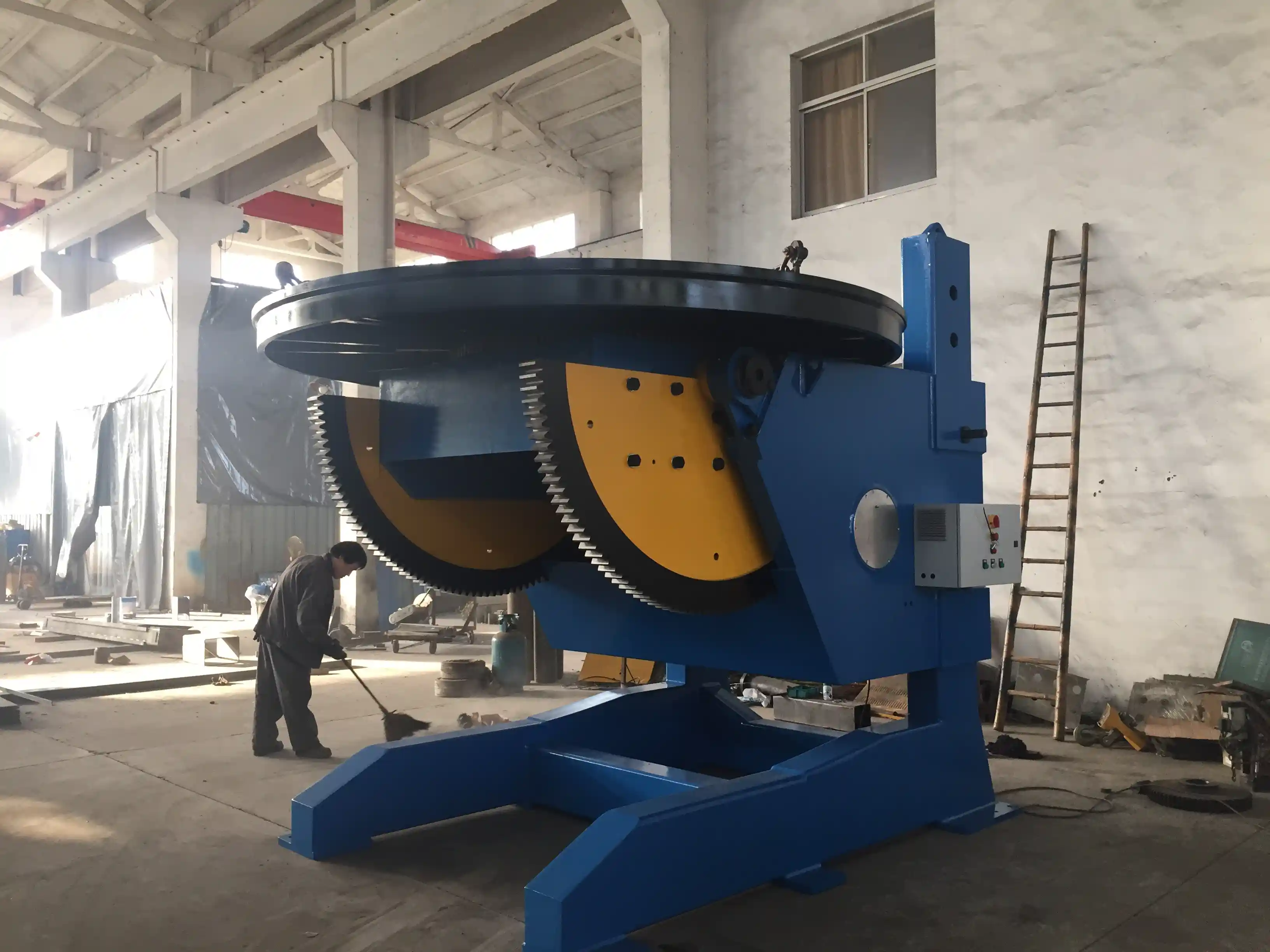
A third factor is machine sizing. A positioner rated for 30 tons can handle nearly any job in a medium fabrication shop, so shops buy the largest capacity they might need. But that 30-ton positioner has a 3000 mm table diameter and requires a foundation footprint of 4 meters by 5 meters. When 80% of the workpieces are under 5 tons, the oversized machine occupies floor space that could hold a smaller, dedicated cell running continuously. The excess capacity generates no revenue. It generates WIP because the large machine becomes a shared resource that departments queue for.
Equipment Layout Decisions That Eliminate Buffer Inventory
The single most effective move I have seen in fabrication shops is converting from a departmental layout to a product-flow layout. Instead of all cutting machines clustered together, a CNC cutting table is placed adjacent to the first welding station for the product family it serves. The material moves from cut to weld without passing through a staging area.
For cylindrical vessels and tanks, this means pairing a welding rotator set directly downstream of the plate cutting station. The cut shell plates move onto the fit-up rotator in sequence, and the completed shell section rolls directly to the welding station on the same roller system. No forklift movement between operations. No buffer pallets. The rotator becomes both a positioning tool and a material handling system.
This is not just about saving forklift time. It is about making WIP visible and impossible to ignore. When a department has a 24-hour buffer, problems in the upstream process stay hidden for a full shift. When the buffer is one piece, a cutting delay stops the welding cell immediately. That sounds bad, but it forces the shop to solve the cutting bottleneck instead of working around it with inventory. Every lean manufacturing equipment layout I have designed uses this principle: reduce the buffer deliberately until the constraint is exposed, then fix the constraint.
The floor space savings are immediate and measurable. A pressure vessel shop that moved from departmental bays to three product-flow cells reclaimed roughly 30% of its production floor. The space that had been buffer inventory became available for a new assembly station.
Multi-Function Machines That Replace Separate Workstations
A conventional H-beam production line might include separate stations for web cutting, flange cutting, assembly, tack welding, and final submerged arc welding. Each station requires its own footprint, its own operator or material handling system, and its own buffer inventory between operations.
Moderno manipulador de soldaduras with integrated column and boom designs combine multiple functions into one footprint. A single manipulator with 360-degree column rotation and motorized travel can handle longitudinal and circumferential welding on both sides of a beam without repositioning the workpiece. When the manipulator is paired with a head-and-tail positioner on a rail system, the same cell handles fit-up, tacking, and final welding in sequence. What previously occupied three separate floor positions now occupies one.
The table below compares the footprint and buffer requirements of a conventional H-beam setup versus an integrated cell approach.
| Layout Approach | Floor Area (m²) | Buffer Inventory Between Stations | Operators Required |
|---|---|---|---|
| Departmental: separate cut, fit, weld bays | 280-350 | 12-18 hours of production | 4-5 |
| Partial flow: cutting + welding adjacent, fit-up separate | 180-220 | 4-6 hours of production | 3-4 |
| Integrated cell: cut, fit, weld in sequence on rail | 120-160 | Single piece flow | 2-3 |
The same logic applies to CNC cutting. A multi-torch CNC plasma cutting machine with a large table eliminates the need for separate rough-cut and trim stations. One machine does both, and the cut parts move directly to the next operation without intermediate sorting or staging. When we configure a CNC cutting center with multiple torch heads and automatic nesting software, the machine can process different part geometries in sequence without setup changes. That eliminates the batch logic that drives buffer inventory.
Integrating Cutting and Welding into Continuous-Flow Cells
The step beyond adjacent machines is a genuine continuous-flow cell where cutting and welding equipment are physically linked by a common material handling system. This is not a theoretical ideal. It is how modern wind tower production lines operate.
In a soldadura de torres eólicas line, the plate cutting station feeds directly into a rolling station on powered conveyors. The rolled can sections move to a fit-up rotator, then to a girth welding station on the same rail system. The entire sequence from flat plate to welded tower section occurs in a single continuous footprint, typically 60 to 80 meters long but only 8 to 10 meters wide. There is no space for buffer inventory because there is no space between stations that is not part of the material flow path.
This configuration demands equipment that is sized to the product family, not to the maximum possible workpiece. A wind tower section requires a specific diameter range, a specific wall thickness, and a specific weld process. The rotators, manipulators, and positioners in the cell are selected for exactly those parameters. Selecting oversized equipment to handle hypothetical future products would break the continuous flow by introducing excess capacity that must be filled with batch work from other product lines — and that batch work brings back the buffer inventory the cell was designed to eliminate.
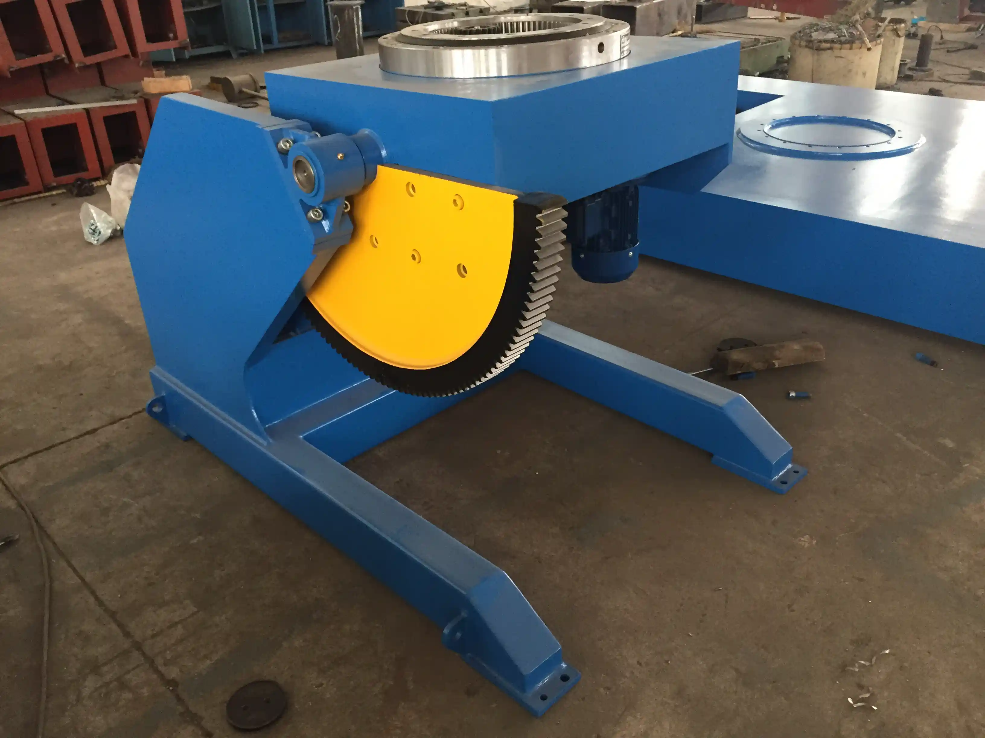
If your program involves components over 5 tons with multiple weld positions requiring both tilt and rotation, it is worth confirming your positioner’s dynamic load rating and axis configuration before committing to a cell layout. A 3-axis positioner with 360-degree continuous rotation and 0 to 90 degree tilt can eliminate the need to re-fixture a heavy component mid-sequence. Send your part drawings and weight data to jay@weldc.com and we can confirm whether your planned equipment arrangement actually supports single-piece flow for your specific components.
Sizing Equipment to Match Takt Time, Not Maximum Capacity
One of the most persistent mistakes I see in fabrication equipment procurement is selecting machine capacity based on the largest or heaviest part on the production schedule. This produces a shop full of oversized, underutilized machines that become shared resources. Shared resources create queues. Queues create WIP.
Takt time, the rate at which finished products must come off the line to meet customer demand, should drive equipment sizing instead. If a shop needs to produce four completed pressure vessels per shift, the cutting station needs to deliver four sets of cut plates per shift, not eight. The welding station needs to complete four circumferential seams per shift, not six. Equipment sized to takt time is smaller, costs less, and occupies less floor space than equipment sized to maximum capacity.
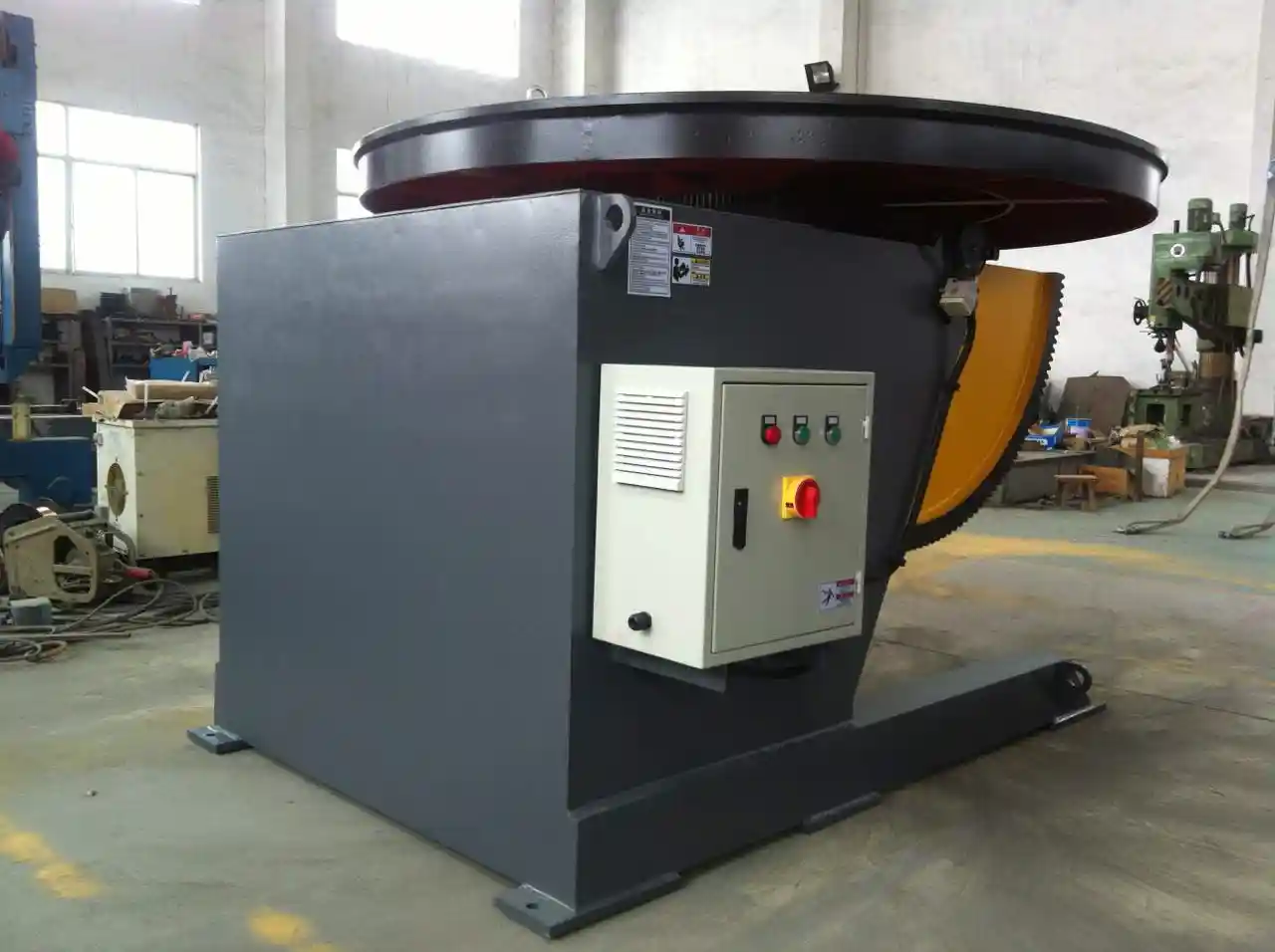
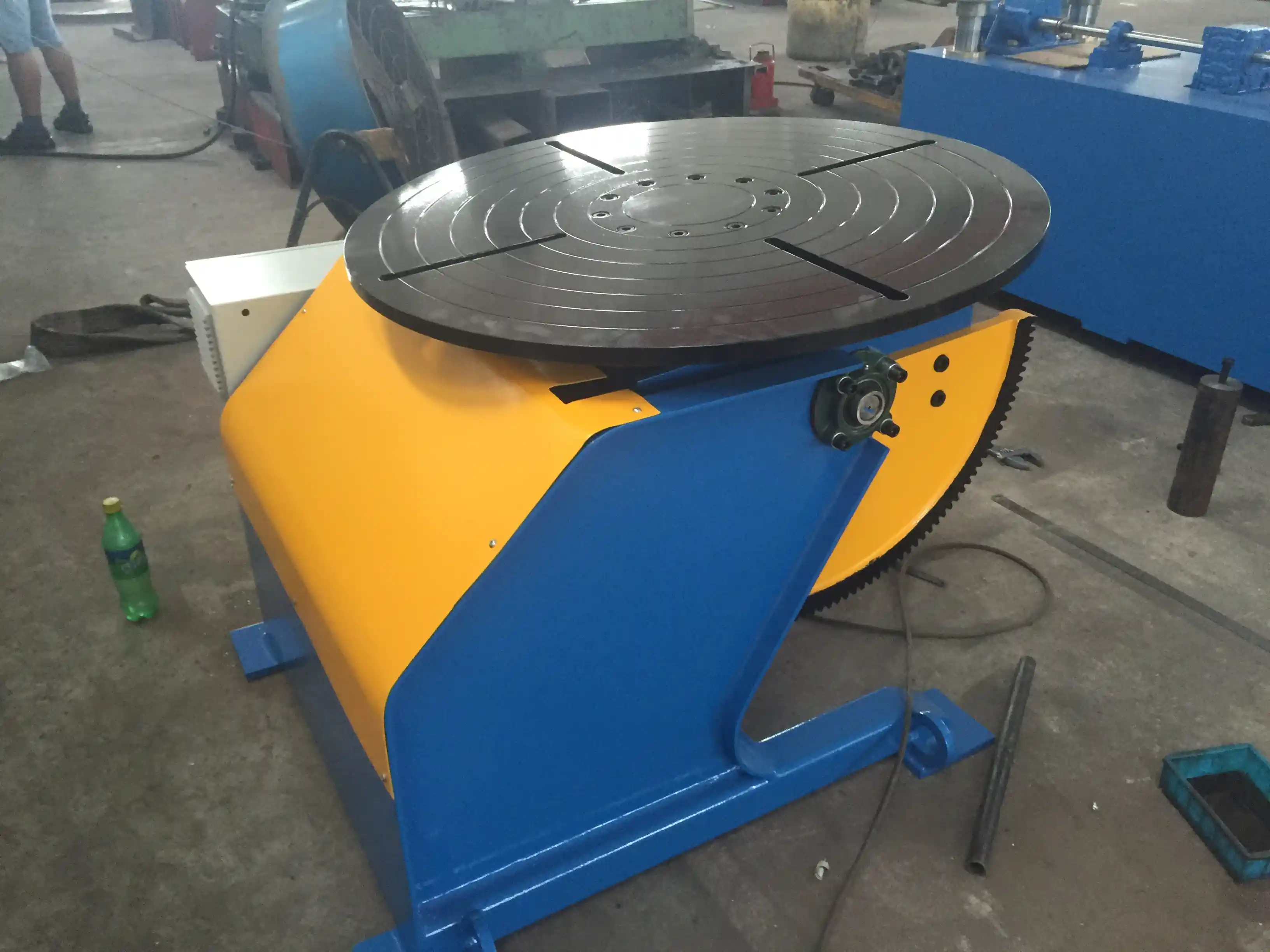
A 5-ton welding positioner with a 1500 mm table diameter suits 80% of the work in a typical pressure vessel shop producing vessels up to 3 meters diameter. For the remaining 20% that require a 30-ton positioner, running those jobs on a separate large-capacity cell preserves the lean flow on the main production line. The alternative, using a single 30-ton positioner for all work, forces every small job through an oversized machine whose footprint could accommodate two 5-ton cells running simultaneously. The total output per square meter is dramatically lower with the single oversized machine.
This principle extends to all equipment categories. A CNC laser cutting machine with 6 kW of power handles 90% of plate thicknesses in structural fabrication. Buying a 12 kW machine for the occasional 40 mm plate job adds capital cost and floor space that dilute the return on every other square meter in the shop. A separate flame cutting station for thick plate, placed in its own cell for heavy section work, preserves lean metrics on the primary cutting line.
The rule is simple: size for the routine, build a separate path for the exception. Every square meter dedicated to equipment that is oversized for daily production is a square meter that cannot host a second cell producing revenue.
What a Lean Fabrication Line Looks Like in Practice
Consider a structural steel fabricator producing H-beam columns and beams for commercial construction. The conventional layout places a CNC plasma cutter at one end of the shop, a flange cutting station 20 meters away, an assembly fixture in another bay, and a welding station with a gantry welder in yet another area. WIP accumulates at every handoff.
A lean equipment configuration rearranges the same production volume into a single linear cell. A multi-torch CNC cutting table handles both web and flange parts in one program. The cut plates move by roller conveyor directly to an H-beam assembly machine that fits the web and flanges together without tack welding. The assembled beam transfers on the same conveyor line to a submerged arc welding station equipped with a twin-wire gantry. The welded beam exits the cell at the straightening station, then moves to shot blasting. Total linear distance from raw plate to finished beam is approximately 40 meters. Total floor area is roughly 30% less than the conventional layout. WIP in the cell at any moment is exactly the number of beams physically on the conveyors — typically three to five, compared to the 20 to 30 beams that accumulate in buffer zones in a departmental layout.
The equipment in this cell is not exotic. It is standard CNC cutting, assembly, and welding machinery. The difference is how the machines are arranged and how the material flows between them. The cell does not require a new building. In most cases, it requires rearranging existing equipment and adding roller conveyors or rail systems to connect stations that were previously separated by forklift aisles.
The output gain comes from eliminating the non-value-adding time between operations. When a beam waits 12 hours between cutting and welding in a departmental layout, that 12 hours is pure WIP. In the cell configuration, the beam moves from cut to weld in under 30 minutes. The welding station is not faster. The cutting station is not faster. The space between them is simply gone, and with it the WIP that occupied it.
Common Questions About Lean Equipment Configuration
Will lean equipment layout work for high-mix, low-volume fabrication?
It depends on the degree of mix. If your product range falls within common dimensional bands — say, beams from 400 mm to 800 mm depth, or vessels from 1.5 meters to 4 meters diameter — a single cell with adjustable tooling handles the full range without batch changeover delays. If the mix spans from small brackets to 60-ton bridge sections, two or three product-family cells make more sense than one universal cell. The key is to group products by process similarity, not by customer order, and to equip each cell for its product family’s specific dimensional range rather than for theoretical maximums.
How much WIP reduction is realistic for a medium-sized structural steel shop?
In the shops where I have implemented lean equipment layout changes, WIP reduction of 35% to 50% is typical within the first six months. The biggest improvements come from eliminating the buffer between cutting and fit-up, which is almost always the largest single WIP accumulation point in a structural shop. Secondary gains come from linking welding and straightening into a continuous sequence, which removes the post-weld staging area. The remaining WIP is the small number of pieces physically in process at any moment, which is a structural minimum rather than a target for further reduction.
Does lean equipment cost more than conventional machines?
The equipment itself is typically the same cost or slightly less, because sizing to takt time rather than maximum capacity often means selecting smaller, less expensive machines. The investment difference is in material handling — roller conveyors, rail systems, or automated transfer carts that connect stations. These add 10% to 15% to the total equipment budget in a typical cell, but the payback from reduced forklift requirements, eliminated buffer inventory, and reclaimed floor space usually covers that increment within 12 to 18 months of operation.
Can existing fabrication shops retrofit for lean flow without a new building?
Almost always yes. The most space-constrained shops benefit the most from lean equipment configuration because they have the least room to waste on buffer inventory. Start by mapping where WIP actually sits on the floor for a full shift. The largest accumulation zones identify where to place the first connected cell. Often, simply moving two machines adjacent and adding a short roller conveyor eliminates the largest buffer. A complete shop rearrangement may take a weekend shutdown, but it rarely requires structural changes to the building. The floor space you need is already there — it is just occupied by WIP instead of value-adding equipment.
What equipment features matter most for lean cell design?
The features that enable single-piece flow are not the highest-spec options. They are things like powered roller beds on rotators so the workpiece transfers without a crane, motorized travel on welding manipulators so the boom moves to the workpiece rather than the workpiece moving to the boom, and PLC controls with preset programs so changeover between product variants happens in seconds rather than minutes. These features cost incrementally more but determine whether a cell actually achieves continuous flow or reverts to batch operation. If you are evaluating equipment for a lean cell, share your production targets and part range with a supplier who can identify which configuration options enable flow for your specific workpieces — reach out at jay@weldc.com or call +86-510-83555592 with your part drawings and daily output requirements.
Floor space in a fabrication shop is too expensive to use as a warehouse for work that should already be completed. Lean manufacturing equipment layout is not about buying faster machines. It is about removing the empty space between them where WIP accumulates, and sizing the machines to the work that actually flows through them each shift. In every shop where I have applied these principles, the factory did not get larger. The output just started moving.
Se estiver interessado, consulte estes artigos relacionados:
Desalinhamento excessivo na soldadura de condutas: Solução de posicionamento de precisão com plataforma giratória da Wuxi ABK Welding
Valor de aplicação excecional: como os posicionadores de soldadura de altura fixa impulsionam os avanços na indústria offshore e na construção naval (Parte 2)
Baixa eficiência na soldadura em grupo de tubagens: como os suportes de rolos inteligentes aumentam a produtividade em 50%
Problemas de soldadura de torres eólicas novamente: Como os rotadores inteligentes da linha de crescimento aumentam a produtividade por 50%
Welding Rotator Precision Automation for Industrial Fabrication: Expert FAQ Guide