Membrane Panel Welding Machine Product Introduction
The standard membrane panel welder is engineered for high-performance fabrication, featuring a 1600mm working width and 4 welding torches utilizing advanced submerged arc welding (SAW) technology. This configuration is widely preferred due to its exceptional productivity, cost-efficiency, and compliance with transportation limits. However, ABK offers fully customizable welding solutions, adapting to specific requirements in panel width, welding head count (2–6 torches), and hybrid SAW/MIG-MAG processes, powered by industry-leading Lincoln PowerWave® systems.
1. Core Technical Advantages
① High-Efficiency Welding System
-
4× Lincoln PowerWave® AC/DC Twin-Wire SAW Systems ensure ultra-high deposition rates (≥28 kg/h per torch).
-
Stepless welding speed adjustment (400–1200 mm/min) for optimized performance across 3–12mm panel thicknesses.
-
Auto-seam tracking (±0.5mm precision) guarantees consistent weld quality.
② Robust Structural Design
-
Modular Q690 high-strength steel frame with stress-relieved construction for long-term durability.
-
Dual HIWIN C3-grade linear guide rails ensure smooth, ±0.2mm/m positioning accuracy.
-
Hydraulic clamping system (21 MPa pressure) secures panels firmly during welding.
③ Intelligent Control System
-
Siemens SIMATIC HMI touchscreen with 50+ preloaded welding profiles for rapid setup.
-
Real-time monitoring of welding current/voltage, flux recovery, and machine temperature.
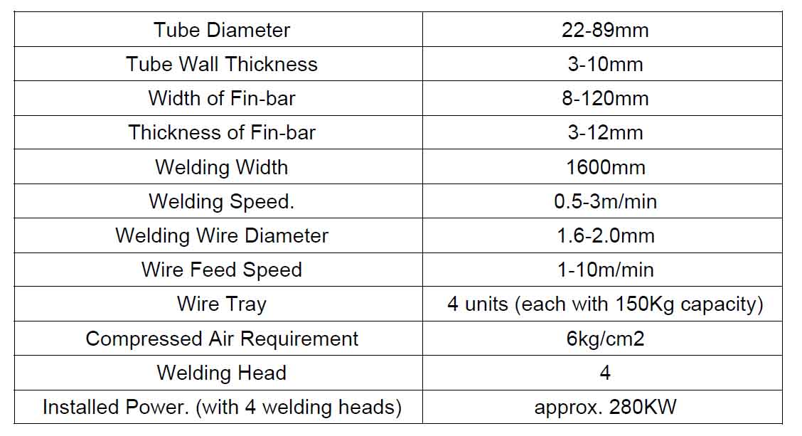
2. Standard Technical Specifications
| Parameter | Specification |
|---|---|
| Panel Thickness | 3–12 mm |
| Welding Process | Twin-Wire SAW |
| Wire Diameter | 2.4 / 3.2 mm (optional) |
| Power Capacity | 4×650A (100% duty cycle) |
| Air Pressure | 0.6 MPa, 200 L/min |
3. Customization & Automation Upgrades
-
Extended Working Width (up to 2500mm) for large-scale panel fabrication.
-
Hybrid Welding (SAW + MAG) for multi-process compatibility.
-
Automated Loading Robot (500kg payload) reduces manual handling.
-
AI Vision Inspection for real-time weld defect detection.
-
MES-integrated Digital Dashboard for production analytics.
4. Economic & Operational Benefits
-
400% higher efficiency vs. manual welding.
-
15–20% material savings with optimized flux and wire consumption.
-
70% labor reduction—only 1 operator required per shift.
-
ROI ≤8 months in two-shift operations.
5. Key Industry Applications
-
Power Plants: Water wall panel welding for boilers.
-
Chemical Vessels: Compartment diaphragm fabrication.
-
Shipbuilding: Bulkhead panel assembly.
-
Steel Construction: Curtain wall substrate welding.
ABK’s membrane panel welding machine integrates cutting-edge SAW technology, modular automation, and smart controls, making it the preferred choice for high-output, precision welding applications.
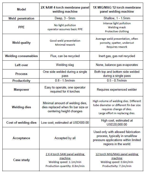
Comparison Table between SAW and MIG/MAG we hope would help you better decide on your investment
Overview of Specification
Membrane Panel Welding System
A basic membrane panel production line consists of 4 basic equipment. They are:
– Membrane panel welding machine
– Fin bar calibration machine
– Tube polishing machine
– Panel bending machine
Introduction
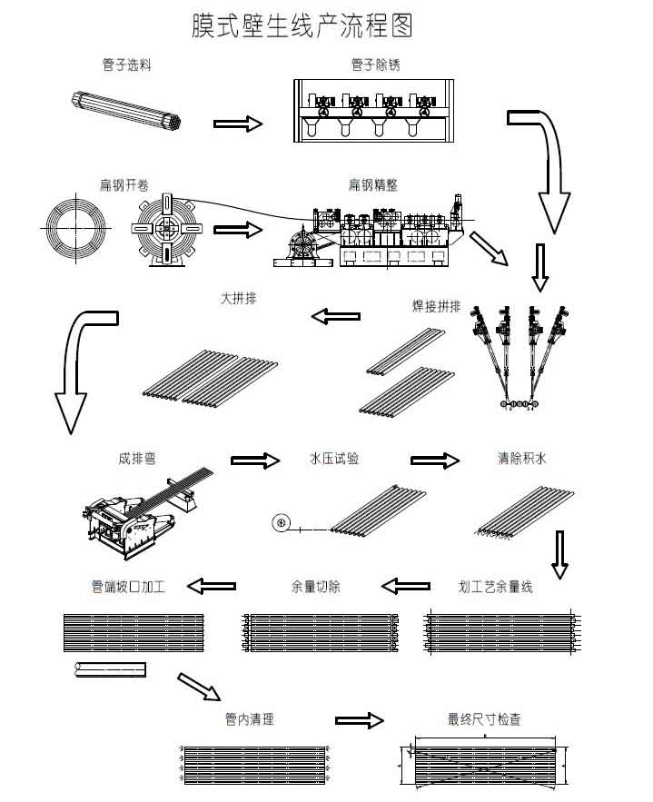
1) The first steps are i) Tubes are protected against rust and corrosion by a protective layer, this prohibits welding and requires them to be “cleaned” by either polishing or sand blasting. ii) Fin bars are required to be calibrated or sized to attain the desired consistency in a panel’s final dimension.
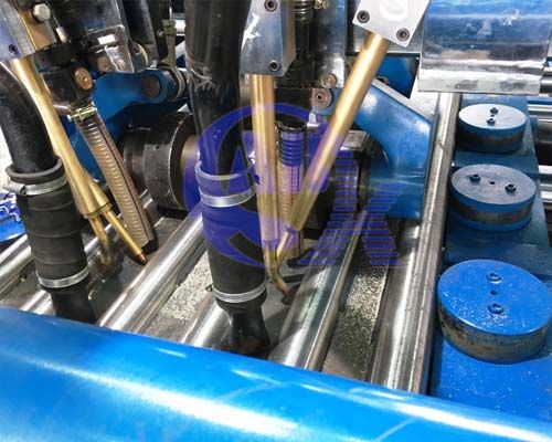
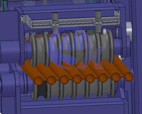
2) The polished tube and fin bar then enters the panel welding machine to be joint by welding.
An example of the typical sequence of welding a 10 tubes membrane panel.
i) Pairs are joint and accummulated. It’s essential to note: a) Always maximize the 4 torches when possible for maximum efficiency. b) To minimize the change in machine setting.
Step One
– Pairs are joint in this manner O–OO–O utilizing all 4 torches of the welder
– Accummucate multiples of O-O
Step Two
– With the completed pairs O-O, take 3 pairs and joint in becoming 6 as seen here O-O–O-O–O-O still utilizing all 4 torches of the welder
Step Three
– With the completed 6 tubes panel O-O-O-O-O-O, joint to it 2 completed pairs from step one. Still, we are utilizing all 4 torches of the welder
– O-O–O-O-O-O-O-O–O-O We now have a 10 tubes panel.
You should always remember!!! To avoid distortion, it’s important to maintain a balanced heat input. To achieve this, firstly we maintain all 4 torches to have an equal input current and voltage setting, secondly we always weld at a position that’s equal distance apart.
8 Tubes panel
For an 8-tube membrane panel, follow these steps while maintaining equal spacing between components:
- Step 1 & 2:
- Complete initial tube and fin bar alignment as per standard procedure.
- Step 3 (Modified for 8 Tubes):
- Instead of pairing tubes, place a single tube and fin bar on both outer ends of the 6-tube base structure.
- Final configuration: O─O─O─O─O─O─O─O (8 evenly spaced tubes).
Production Capacity Analysis
Our 4-torch membrane panel welder delivers:
✔ Experienced Operators: 1,000+ meters of weld per 8-hour shift
✔ New Operators: ~500 meters (efficiency improves with training)
Industry Benchmark
- Large boiler manufacturers typically operate 8–10 welding machinesfor mass production.
How do we position a fin bar during the welding process
This is a question I get a lot, let us discuss this a little.
There are mainly 2 methods commonly seen or used in the industry. Please refer to the picture below:
Method 1
There are typically 2 sets of the above dies/mould installed at the front and back to hold into position the tube and fin bar. This would place the fin bar in the exact desired position during the welding process. However, every change of tube diameter, fin bar width, fin bar thickness would require an extensive replacement/change of the dies. This can be a tideous and time consuming process, often very expensive. Perhaps for manufacturers of a fixed design, without any custom orders or design changes could they not be required to change such dies.
Method 2
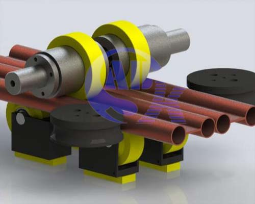
Our innovative quick-change fin bar alignment system ensures precision while offering unmatched flexibility:
- Interchangeable Tooling (Yellow Components)
Top & Bottom Dies:
- Removable/replaceable design for rapid adaptation
- Standardized machining for cost-effective production
2.Multi-Point Support Structure
| Component | Function | Adjustability |
| Bottom Shim Plate | Sets fin bar height | Replaceable thickness (0.5–5mm steps) |
| Top Guide Ring | Controls vertical alignment | Slide-adjustable clamp mechanism |
| Roller Wheels | Supports width variations (2x support) | Quick-swap for different fin widths |
- Cost-Effective Customization
Full die sets for all standard sizes: $200–500 per set
Typical variants in stock:
- Tube diameters:25mm, 38mm, 50mm
- Fin widths:10mm, 15mm, 20mm
- Thicknesses: 5mm, 2mm, 3mm
Operational Advantages
✅ <5-minute changeover between fin bar profiles
✅ Zero machining delays – dies pre-made for common specs
✅ Error-proof positioning – eliminates manual measurement
Recommended Inventory Strategy
For 24/7 production flexibility, maintain:
- 3x top rings (cover 90% of tube diameters)
- 5x shim plates (0.5mm/1mm/2mm/3mm/5mm)
- 2–3 roller wheel sets (matched to fin width)


