In heavy fabrication, material flow efficiency is determined by one factor more than any other: the path of the largest workpiece. I have seen workshops where managers spend weeks fine-tuning machine sequences only to find that a 20-ton vessel cannot pass between two welding stations, or that the overhead crane cannot reach the far end of a positioner. Material flow layout optimization is not about placing equipment on a grid; it is about designing the movement of steel plates, rolled sections, and assembled components so that every welding manipulator, CNC cutting machine, and positioner serves the natural progression from raw material to finished structure. When that progression respects weight, size, and crane reach, production throughput yields gains that no additional shift hours can match.
What Makes Material Flow Critical in Heavy Fabrication?
In typical medium-to-heavy fabrication shops, material handling can consume 30 % of total production time. Plates arrive at the CNC cutting station, cut parts are moved to fit-up, tack-welded assemblies are transported to a welding station, and finished components wait for inspection. Without a layout designed around the largest component, work-in-progress accumulates, cranes become bottlenecks, and operators spend more time moving steel than welding it.
The heavier the product, the more layout dictates flow. A shop producing wind tower sections with diameters exceeding 4 meters cannot simply place a welding positioner in a corner; the part must rotate freely, the crane must have clear travel paths, and there must be space for the operator to access both longitudinal and girth seams. When layout keeps every operation’s output in the input zone of the next, cycle times drop without capital expense. We have measured throughput improvements of 15–20 % after reconfiguring stations to align with the logical process flow.
What Layout Constraints Affect Heavy Fabrication Shops?
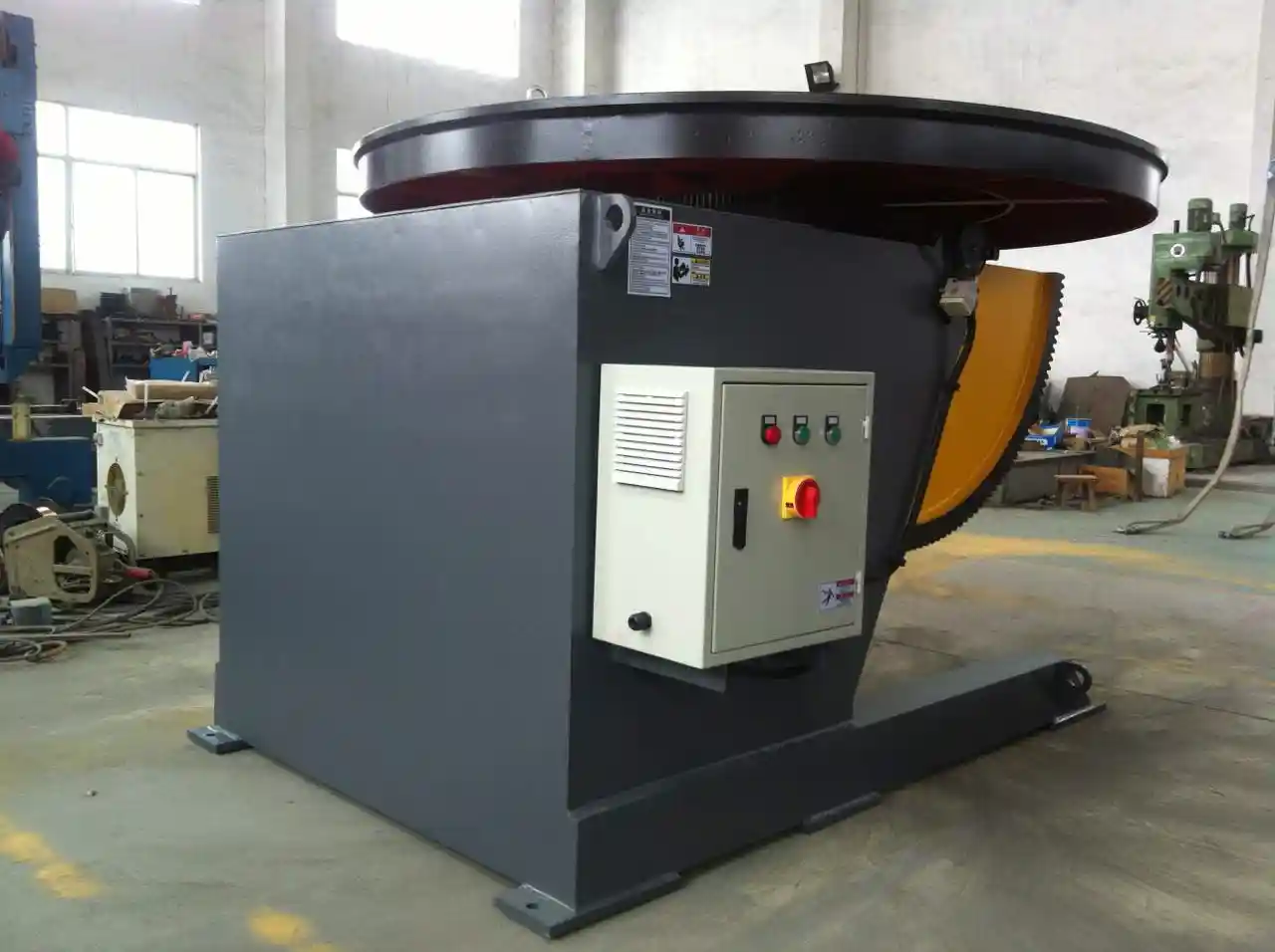
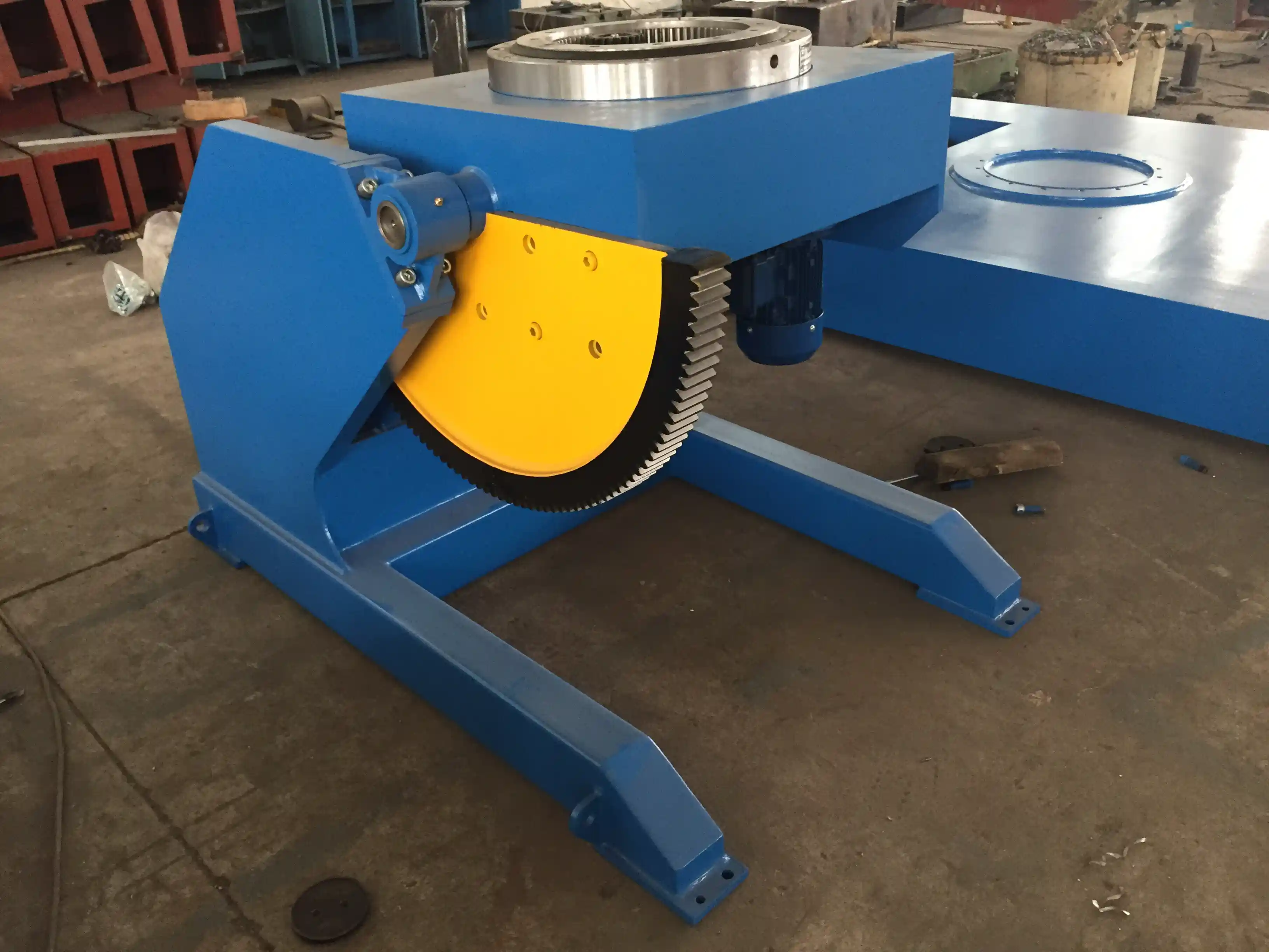
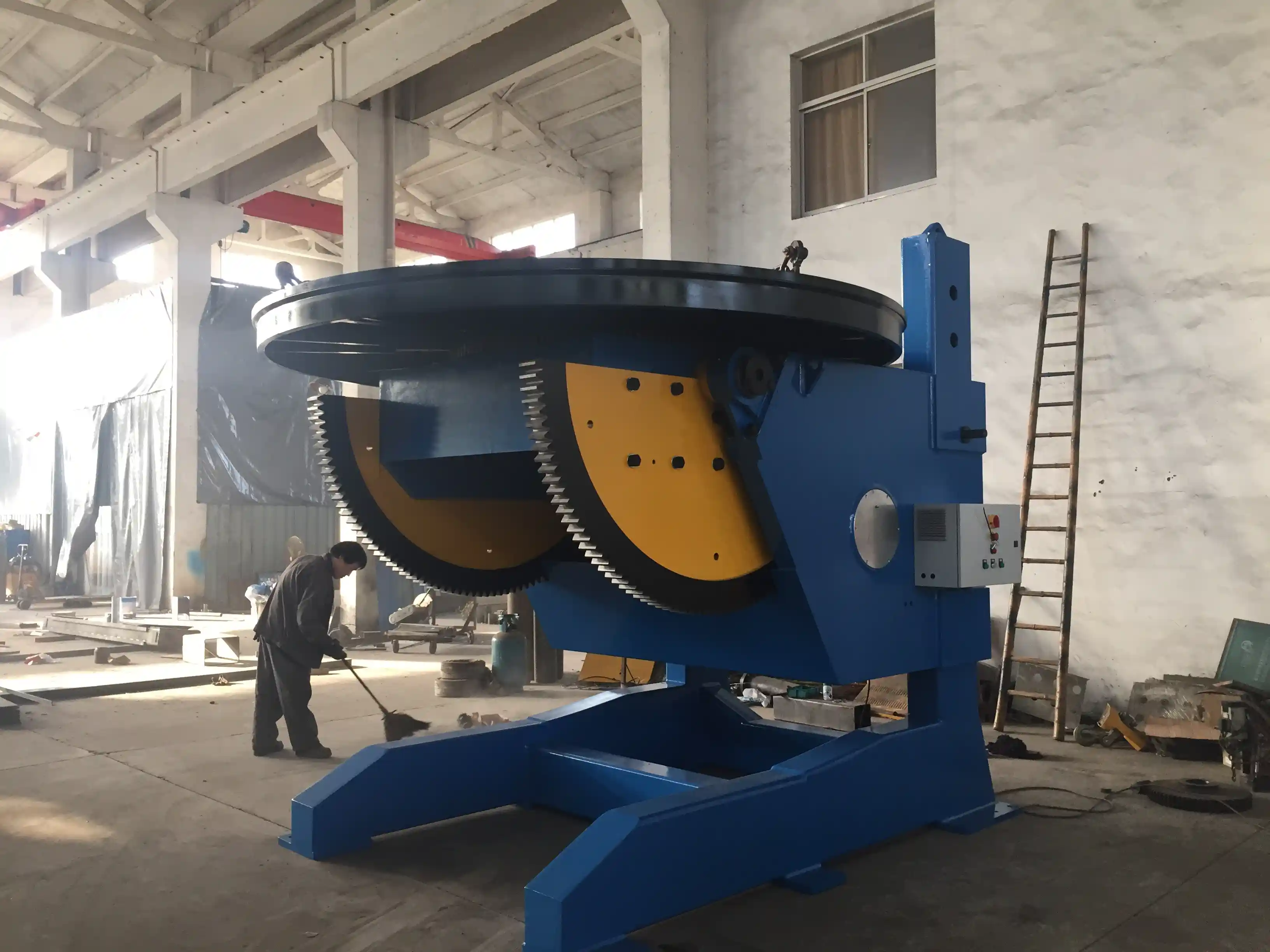
The physical footprint of heavy welding equipment often sets minimum column spacing. For example, the ABK 30‑ton adjustable height welding positioner, with a worktable at 2 meters height and an L‑support arm extending 800 mm, requires a clear zone of at least 5 × 6 meters when turning a vessel. A 100‑ton adjustable positioner with an 1800 mm worktable demands a 7 × 8 meter area plus a dedicated reinforced concrete foundation.
The table below compares typical positioner models and their approximate layout requirements:
| Positioner Model | Load Capacity | Worktable Diameter | Approx. Floor Space (m) | Required Crane Lift |
|---|---|---|---|---|
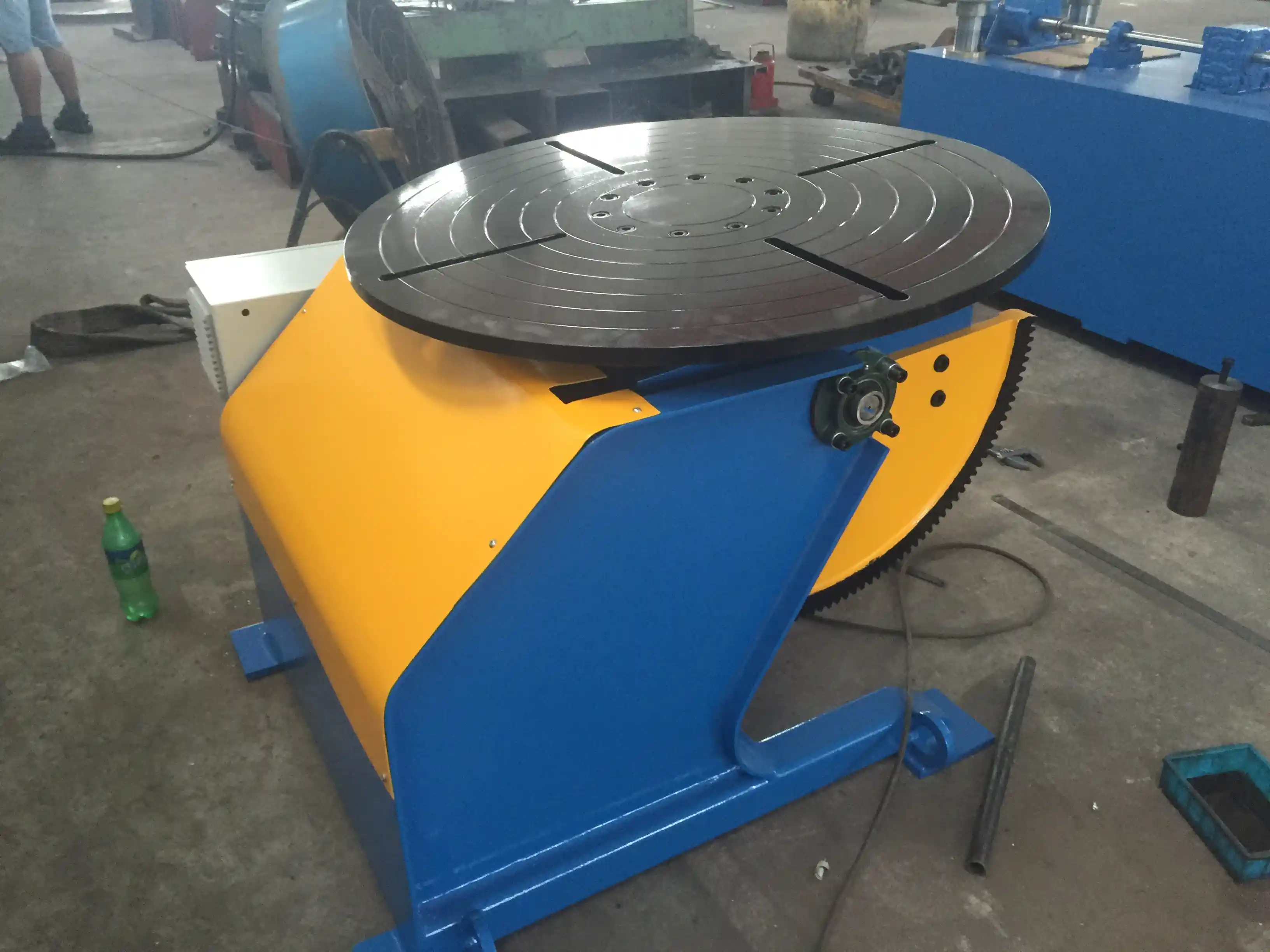
| HBJ‑10 | 1 ton | 1200 mm | 2.5 × 2.5 | 2 tons |
| HBJ‑20 | 2 tons | 1200 mm | 3.0 × 3.0 | 3 tons |
| HBJ‑50 | 5 tons | 1500 mm | 4.0 × 4.0 | 10 tons |
| 30‑ton Adjustable | 30 tons | 600 mm (L‑support 800 mm) | 5.0 × 6.0 | 50 tons |
| 100‑ton Adjustable | 100 tons | 1800 mm | 7.0 × 8.0 | 120 tons |
(The 30‑ton model uses an L‑support structure, so the effective footprint includes the turning envelope.)
Beyond positioning equipment, floor load capacity is often the limiting factor. A 30‑ton positioner’s dynamic load can impose concentrated forces of over 15 tons per square meter on its foundation points. Shops built for light fabrication may require reinforced pads, which can alter the layout plan. I have seen a project where the initial layout placed a 5‑ton positioner over a utility trench; after months of cracking, the whole station had to be relocated, causing weeks of downtime. Consulting load charts before finalizing positions avoids these expensive corrections.
What Floor Load Capacity is Needed for a 30‑Ton Positioner?
A 30‑ton positioner with a 6‑meter vessel can generate overturning moments requiring a foundation pad with at least 20 tons/m² bearing capacity. ABK’s engineering team can supply load distribution diagrams for each model, which your civil engineer should review before pouring concrete.
How to Coordinate Welding Manipulators, Positioners, and CNC Cutting Machines
In a well‑coordinated layout, the cutting machine’s output buffer directly feeds the fit‑up station, which aligns with the positioner and manipulator. For longitudinal seams on cylindrical vessels, the welding manipulator travels on a rail parallel to the vessel axis. The ABK LH4580 manipulator offers 4500 mm horizontal travel and 8000 mm vertical reach, so the rail must be at least 5 meters long and parallel to the positioner’s centerline within ±2 mm. The positioner rotates the vessel while the manipulator head moves linearly; if the rail is misaligned by even 5 mm, the arc gap becomes inconsistent, causing weld defects.
We recommend placing the CNC cutting station upstream of the fit‑up zone, with cut plates stored on a roller conveyor that leads directly to the positioner. This minimizes crane lifts. The manipulator’s boom should never be used to pull plate into position; its function is strictly welding. For H‑beam lines, the sequence is different: the CNC plasma cutter processes web and flange plates, which are assembled on an H‑beam assembly machine, then tack‑welded and moved to a through‑type welding station. In that case, the layout is linear, with the beam axis aligned with the building columns.
How Do I Align a Welding Manipulator with a Positioner?
Place the positioner first, oriented so the workpiece axis is parallel to the building’s long dimension. Then install the manipulator rail parallel to that axis, using a laser tracker to verify that the rail is true within ±0.5 mm per meter. Confirm that the manipulator head’s vertical travel can cover the full weld path without re‑positioning the vessel. For a 6‑meter‑long shell, the LH4580’s 4500 mm horizontal travel might be insufficient, requiring a longer‑stroke model like the LH8080. Contact ABK with your part dimensions for a recommendation.
If your project involves vessels longer than 8 meters, the required manipulator horizontal travel may exceed standard models. Send your part length and diameter to jay@weldc.com and we will confirm the right boom and rail configuration.
How Do You Plan Layout for Floor Load and Crane Access?
Before finalizing any equipment placement, examine the shop’s crane coverage diagram. Every heavy positioner, assembly table, and cutting machine must be within the hook range of an overhead crane rated for the heaviest subassembly. A 30‑ton positioner requires a 50‑ton crane for safe handling of 25‑ton vessels; the crane’s hook height must clear the positioner at full tilt (up to 2 meters). If the crane cannot reach the far side of the positioner, the layout fails.
Floor reinforcement is equally critical. The 100‑ton adjustable positioner’s base plate imposes a pressure of over 3 MPa, which exceeds most industrial floor slabs. A separate 1‑meter‑thick reinforced pad is usually necessary. In one configuration for a wind tower shop, we offset the positioner 2 meters from the building column lines to allow for pad formwork and vibration isolation. That early planning prevented later resonance issues during welding.
Do I Need to Reinforce My Floor for a 5‑Ton Positioner?
A 5‑ton fixed‑height positioner like the HBJ‑50 typically does not require a dedicated pad if the floor is at least 150 mm thick and reinforced. However, if the workpiece is long and top‑heavy, dynamic tilting can cause rocking, so we recommend bolting the base to the slab. For any doubt, share your floor slab drawings with ABK; we will verify compatibility with the specific model.
What Can We Learn from Wind Tower and H‑Beam Production Layouts?
In a wind tower shop I helped design, the layout centered on a 100‑ton positioner with dual welding manipulators. The plate shot‑blasting and CNC cutting area was located at one end, cut plates moved by overhead crane to the fit‑up rotator, and the assembled shell traveled to the main positioner station on rail‑mounted trolleys. Because the vessel rotated in a 7‑meter‑diameter circle, we kept all adjacent equipment 2 meters outside that circle so the crane hook had unobstructed access. That layout sustained a production rate of one complete tower section per shift.
For an H‑beam line producing sections up to 800 mm, the layout followed a straight line: incoming plate → CNC plasma cutting → assembly machine → tack station → welding gantry → straightening machine. The total line length was 35 meters. By aligning the line parallel to the building’s 40‑meter length, the crane traveled only between the material storage and the line feed, avoiding cross‑traffic with other production. That arrangement reduced material handling time by roughly 20 % compared to an earlier U‑shaped layout.
How Does Layout Differ for Different Product Types?
Vessel‑type products (tanks, pressure vessels) require circular flow around a positioner, while beam‑type products (H‑beams, box girders) need linear flow. When your shop mixes both, separate the areas physically, with dedicated cranes for each zone to prevent interference. ABK can model both configurations and suggest crane coverage improvements.
Optimize Your Facility’s Material Flow Today
A layout that works in theory will fail in practice if crane reach, floor capacity, and equipment dimensions do not match real workloads. The most productive heavy fabrication shops I have seen treat layout as a continuous improvement activity, not a one‑time drawing.
Send your facility dimensions, crane specifications, and a list of the largest parts you produce to jay@weldc.com, or call +86‑510‑83555592. Our application engineers will provide a preliminary layout recommendation with equipment placement tailored to your production flow — no charge, no commitment.
Common Questions About Material Flow Layout and Equipment Coordination
How much floor space do I need for a typical H‑beam welding line?
For medium H‑beams (400–800 mm section height), a 30‑meter by 10‑meter area can house the cutting, assembly, and welding stations in linear arrangement. However, if you also produce box girders or add straightening, allow an extra 5 meters of length. Our team can supply a model‑based space plan once you provide your part range.
Can I reconfigure my existing layout without major construction?
Often yes. Moving lighter equipment like 1‑ton positioners and rearranging conveyor stands can improve flow without civil works. Heavier positioners over 10 tons may require floor reinforcement, but many shops can add localized pads without disrupting the entire floor. We have helped plants re‑layout stations during weekend shutdowns.
What is the most common layout mistake in heavy fabrication?
Placing the positioner too far from the fit‑up area, or the CNC cutting machine in an adjacent bay, so that parts travel 30 meters or more before welding. Every extra meter adds a crane cycle and increases the chance of damage. Keep cutting and fit‑up within 10 meters of the positioner whenever possible.
Do I need a new crane for a 30‑ton positioner?
If your current crane has a 50‑ton capacity and its hook can reach the positioner’s turning envelope at the required height, then no. If the crane is undersized or its travel path is blocked, you will need to either upgrade the crane or relocate the positioner. Share your crane drawings with us; we will verify compatibility.
How does ABK help with layout planning?
We provide dimensioned equipment 3D models (STEP/IGS) that your designer can place directly into your facility model. Additionally, our engineers can review your proposed layout and identify interferences, crane reach issues, and floor load mismatches. This service is included with any equipment inquiry. Send your part requirements to jay@weldc.com and we will prepare a functional layout together.
If you’re interested, check out these related articles:
Achieving Perfect Welds on Large-Diameter Pipes with Professional Rolling Equipment
Pipe Rotators and Turning Rolls: Essential Equipment for Modern Pipeline Fabrication
Low Efficiency in Pipeline Group Welding: How Intelligent Roller Racks Increase Productivity by 50%