I’ve walked into shops with a common irony: the plasma cutter finishes a plate in minutes, but the part then sits for hours waiting for the welding booth to free up. The real bottleneck isn’t cutting—it’s how you move, position, and weld after the arc stops. Integrated cutting and welding lines, where processed material flows directly to a ready manipulator or positioner without intermediate storage, can double throughput. But making that work demands equipment selection decisions that go beyond horsepower. Over twenty years of configuring automated lines at Wuxi ABK Machinery, I’ve found that matching cutting discharge to welding station capacity, not chasing higher cutting speeds, determines whether a line meets its promised production rate.
Equipment Configurations That Enable Integrated Cutting and Welding
A continuous flow line starts with the cutting station—plasma, laser, or water jet depending on material and thickness—but the integration’s core lies in the welding handling system. Rather than stacking cut parts on a pallet, they move directly to a column and boom manipulator (our LH series, for example) or a multi-axis positioner. The manipulator’s boom travel and column rotation let it serve several welding positions in a cell, so a part cut upstream can be positioned within minutes. The LH4580, with 4500 mm horizontal reach and 8000 mm vertical travel, covers a work zone spanning several meters, and with a trolley on rails, it services multiple workstations without needing a crane. This eliminates the crane bottleneck I’ve seen in many shops.
To select the right manipulator, consider your largest workpiece envelope and required positioning precision. Our LH series uses a high-strength box-beam structure, linear guideways, and cycloidal reducers for stable operation at ±0.1 mm/m accuracy. Table 1 compares a few models to show how travel range scales.
Table 1: ABK Welding Manipulator Specifications
| Model | Horizontal Travel (mm) | Vertical Travel (mm) | Rotation | Boom Speed (m/min) | Trolley Speed (m/min) |
|---|---|---|---|---|---|
| LH8080 | 8000 | 8000 | ±180° | 0.12–1.2 | 0.2–2 |
| LH4580 | 4500 | 8000 | ±180° | 0.12–1.2 | 0.2–2 |
| LH5060 | 5000 | 6000 | ±180° | 0.12–1.2 | 0.2–2 |
| LH3040 | 3000 | 4000 | ±180° | 0.12–1.2 | 0.2–2 |
| LH1235 | 1200 | 3500 | Manual up to 360° | 0.12–1.2 | Manual |
This range means that for a shop producing H-beams up to 800 mm tall, an LH4580 can weld all sides without repositioning the beam, while a smaller LH1235 suits constant-diameter pipe work. The key is matching the manipulator’s work envelope to the typical part sizes within your first-year product mix, not just today’s order.
Matching Cutting Output to Welding Capacity
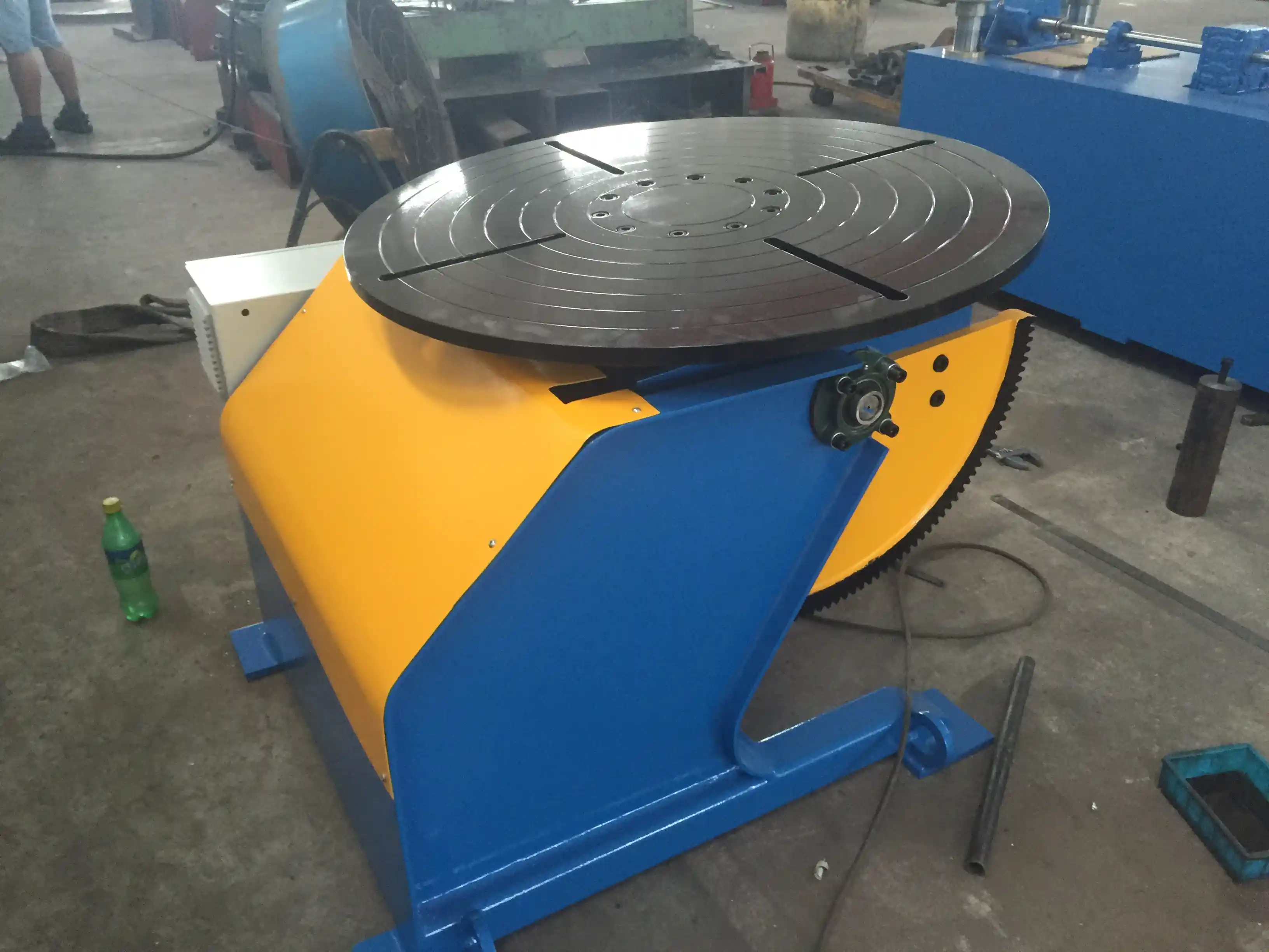
I’ve walked onto production floors where two plasma cutters outran a single welding station, and the area between them became a mountain of unfinished steel. Cutting speed is rarely the true bottleneck—the welding side’s duty cycle, which includes fit-up, tacking, and actual arc-on time, sets the pace. A 1-ton 3-axis positioner (like ABK’s model with ±0.05 mm positioning and 0.02 mm repeatability) can dramatically cut fit-up time because every joint is presented at the right angle without manual jacking. The welding arc then spends more time on the metal and less time waiting for the next part.
When we help customers configure a line, we run a time-motion study: if the cutting station outputs a plate every 15 minutes but the welding cycle (including load/unload) takes 20 minutes, the line produces one finished part every 20 minutes, not 15. You can either add a second welding station or reduce the welding cycle. The latter costs less. Using a positioner with fast-clamp chucks—our self-centering welding chucks with 60 mm jaw travel—can cut clamping time from minutes to seconds. Even the best cutting machines won’t make up for a slow welding downstream, so match capacity there first.
If your line faces plates up to 100 mm thick and you’re uncertain whether plasma or laser cutting will match your welding station’s duty cycle, email your process details to jay@weldc.com or call +86-13815101750—our engineers can run a throughput analysis.
Designing the Material Flow Path Between Stations
The material path—how a cut plate gets to the welding manipulator—often gets designed last, and it shows. I recommend a linear layout with cutting at one end, then a roller conveyor or rail-guided cart system delivering parts to the welding positioner. For large vessels (5 m diameter and up), we’d place a self-aligning welding rotator at the end, with the shell plate rolled in from the cutting bay. ABK’s HGZ-100 standard welding rotator, spanning 1000–5000 mm diameter range and driven by a 5.5 kW motor, handles heavy cylinders while maintaining 0.1 mm/m tracking accuracy thanks to its anti-creep control.
Don’t forget vertical clearance. A column and boom manipulator needs headroom—the LH8080 reaches up to 8000 mm—so your building height must accommodate it. I’ve seen a line delayed because the welding manipulator couldn’t be installed under low ceiling trusses. Early planning of the flow path with accurate equipment dimensions, which we provide at inquiry stage, prevents such costly rework. Sharing your shop layout early is the single most valuable step.
Integrating Positioners and Rotators for Uninterrupted Welding
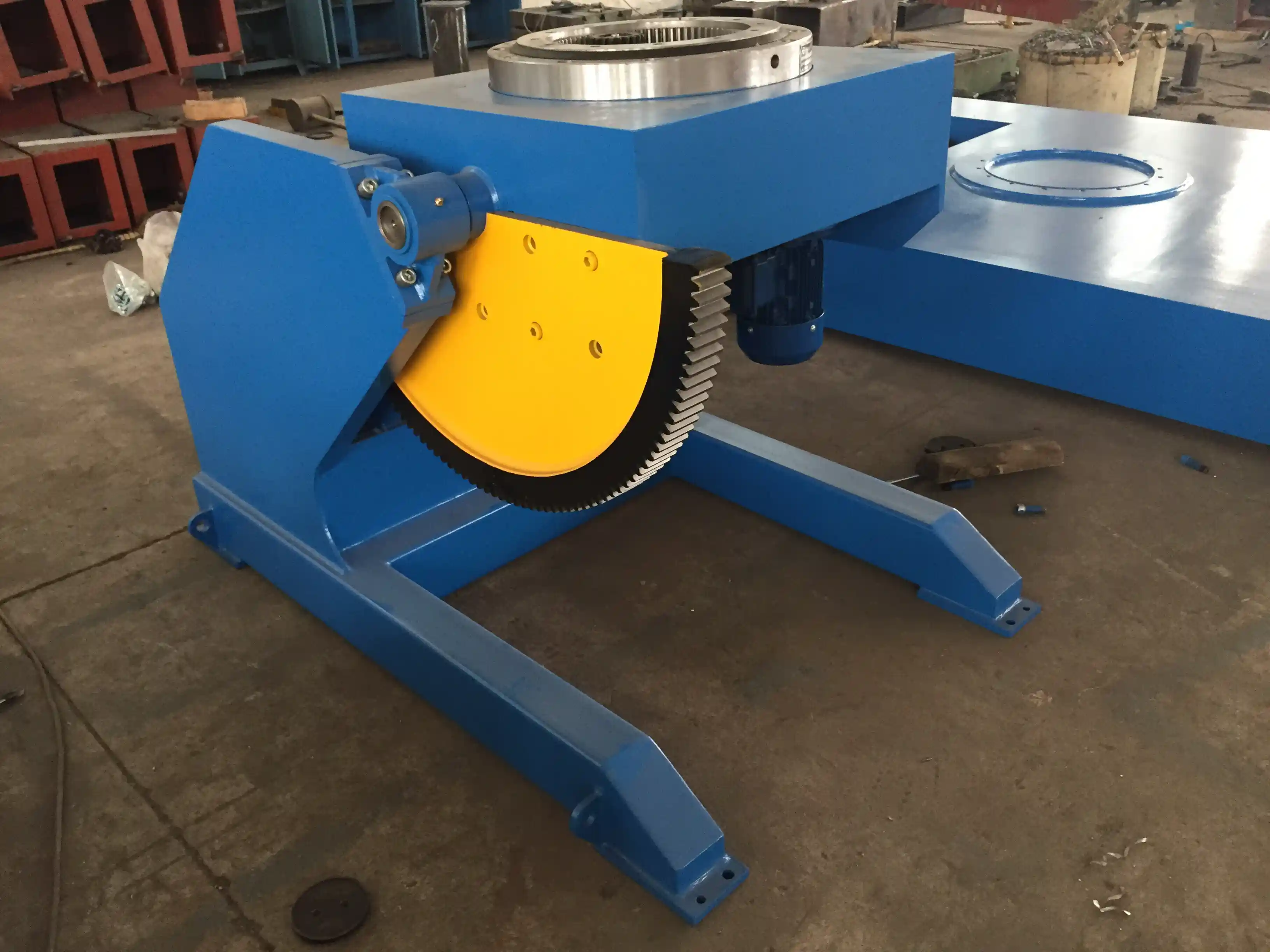
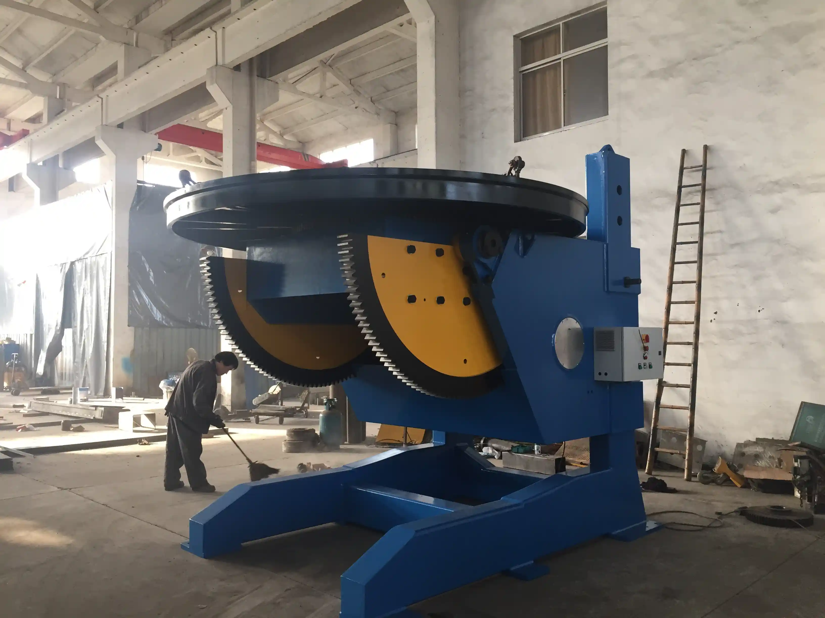
A fixed-height positioner may work for standard parts, but as soon as your product diameters or lengths vary, you need adjustability. Our L-type positioners, like the LHBJ-50 with 5-ton capacity and hydraulic height adjustment (1000–2000 mm), allow quick adaptation between jobs. Table 2 shows how capacity and height range differ across two models.
Table 2: ABK L-Type Welding Positioners
| Model | Load Capacity (kg) | Worktable Diameter (mm) | Height Range (mm) | Tilt Range | Motor Power (kW) |
|---|---|---|---|---|---|
| LHBJ-30 | 3000 | 1500 | 1000–2000 | 0-120° | 1.1 / 2.2 |
| LHBJ-50 | 5000 | 900 | 1000–2000 | 0-120° | 1.1 / 2.2 |
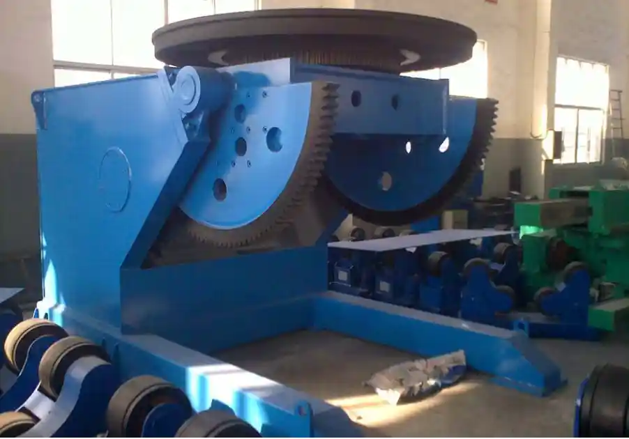
For complex welded structures like excavator booms or wind turbine flanges, a 3-axis positioner (ABK’s 2-ton or 5-ton models) provides rotation, tilting, and turning so you never re-fixture. That reduces part handling between welds, keeping the flow continuous. I’ve found that shops using simple two-roller rotators often add a separate positioner later after they realize the rotator can’t tilt for angled welds. Plan for that flexibility from the start, or at least leave space to upgrade.
Changeover Strategies for Mixed-Production Lines
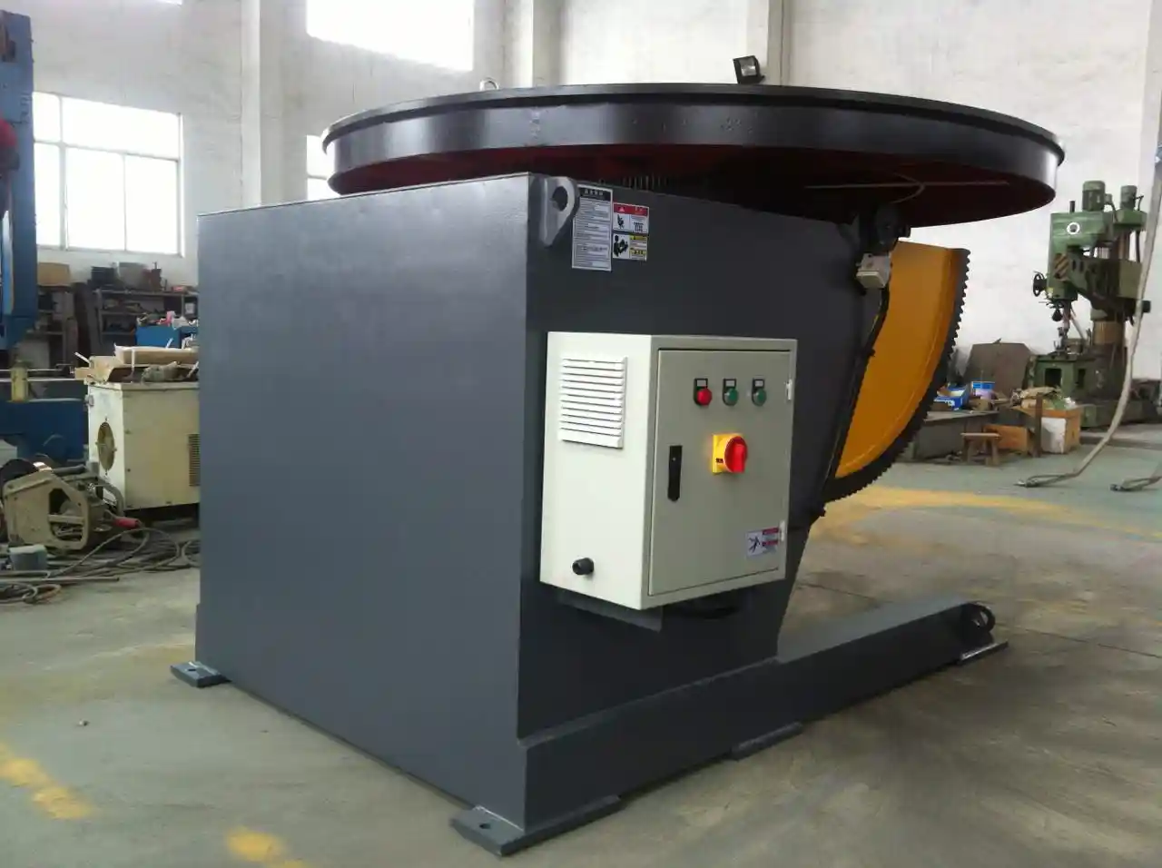
If your shop makes four different vessel diameters and three pipe types in a single week, the line can’t stop for half a day to reconfigure. That’s where programmable controls and modular tooling come in. Our positioners use Siemens PLC with HMI touchscreens storing over 100 preset welding programs. An operator selects a recipe, and the table moves to the correct pre-set angles, saving 20–30 minutes per changeover. Similarly, welding manipulators with motorized cross-slides and flux recovery systems can switch between submerged arc and MIG welding without tool changes.
One approach we’ve implemented is to group similar-diameter jobs on the same shift, reducing the need for major adjustments. If your product mix is too unpredictable, consider a positioner with conductive slip rings and a generous T-slot table that can clamp various fixture plates without re-drilling. I’ve seen a tank fabricator cut changeover time by 40% just by standardizing their mounting interface across product families. The upfront investment in a flexible positioner pays back in weeks, not years, when changeover time is priced correctly.
Moving from Concept to Production: Specifying Your Line
The most frustrating line I’ve watched was a top-tier plasma cutter feeding a welding station that could never keep up, simply because the rotator’s load capacity was undersized. The owner had focused on the cutter’s specs and overlooked that the rotator was struggling with the heavy shells. At Wuxi ABK, we start every line design by listing your heaviest, largest, and most complex part—not the average. From that, we size the welding manipulator, positioner, and rotator to handle the peak.
If you’re planning an integrated cutting and welding line, I’d suggest sending us your part drawings, daily target output, and a sketch of your available floor space. Our team will propose a layout with specific model recommendations, and we can discuss how to phase the investment if capital is staged. Reach our lead engineer directly at jay@weldc.com, or call +86-13815101750. There’s no substitute for an engineering conversation when you’re designing a line that has to run continuously, day after day.
Questions Fabricators Ask About Integrated Cutting and Welding
What’s the minimum production volume to justify a continuous flow line?
It’s less about total volume and more about the cost of work-in-process and floor congestion. For a shop making 20 large pressure vessels a month, the space and time lost to storing partial assemblies often outweighs the cost of a proper rotator and manipulator setup. We’ve seen ROI under 12 months even for monthly runs of a few dozen heavy weldments.
Can a single welding manipulator serve multiple cutting machines?
Yes, if the manipulator has sufficient travel and fast programming. Our LH8080 with 8000 mm horizontal travel and rail-mounted trolley can shuttle between two different cutting discharge points. However, the scheduling logic gets complex—you may need to stagger cut times so the manipulator isn’t caught between jobs. A simple visual signal on the floor works for many shops.
How do you handle different material grades in a continuous line?
Stainless steel and carbon steel shouldn’t share the same handling path due to cross-contamination risk. I recommend dedicated tooling sets or at least separation by shift. The positioner’s stored programs help: you can define a “stainless mode” with adjusted travel speeds and heat control, but physically separating the workflows by day is cleaner.
Does continuous flow require an expensive MES system?
Not necessarily. Many of our lines run with just the built-in PLC coordination and a whiteboard schedule. More advanced monitoring is nice, but if you start simple and add sensors later, you avoid paralysis by IT. The machines we deliver come with IP54-rated control cabinets and straightforward HMI, so operators can manage counts manually.
How long does it take to integrate a cutting and welding line?
From order to production, typically 4–6 months, depending on customization. We handle installation drawings, foundation coordination, and commissioning. The biggest variable is your building readiness; getting the foundation pads poured early makes a huge difference. If your part family includes parts over 30 tons, it’s worth confirming that your floor loading capacity supports heavy positioners—contact us at jay@weldc.com with your factory specs for a site review.
If you’re interested, check out these related articles:
Revolution in Ship Welding: How Welding Positioners Improve Quality and Efficiency
Wind Tower Welding Problems Again: How Intelligent Growing Line Rotators Boost Productivity by 50%
Low Efficiency in Pipeline Group Welding: How Intelligent Roller Racks Increase Productivity by 50%
Workshop Space Too Small? How Column Booms Save 50% Floor Space While Boosting Safety & Efficiency
Achieving Perfect Welds on Large-Diameter Pipes with Professional Rolling Equipment