
Automated welding systems for pressure vessel manufacturing coordinate the welding manipulator, workpiece positioner or rotator, power source, and control system so each seam is produced under repeatable travel speed, torch angle, rotation, and parameter settings. The central reason to automate is not speed alone. It is control. Long shell seams, heavy cylindrical sections, nozzle welds, and repeated circumferential joints are difficult to keep consistent when operators must reposition the vessel and weld at the same time. An automated cell moves the vessel into a predictable position, keeps the weld head aligned, and records the settings that produced the result.
How an Automated Pressure Vessel Cell Is Arranged
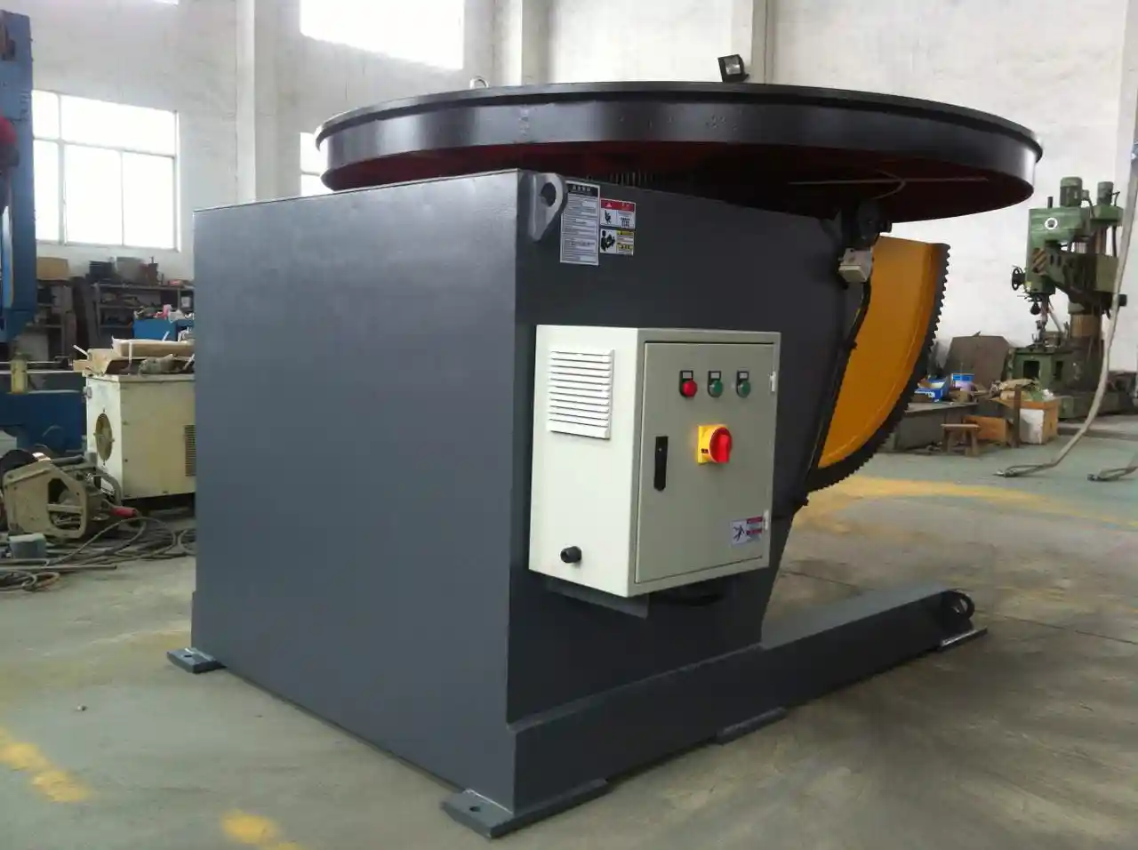
Most pressure vessel automation starts from two tasks: rotating the shell for circumferential seams, and moving the welding head along the shell or girth for longitudinal and circular welds. A welding manipulator carries the torch on a vertical column and horizontal boom. A positioner or rotator rotates the workpiece. The power source and controller coordinate travel speed, rotation, and weld parameters. The arrangement may be a manipulator over a turning roll, a headstock and tailstock positioner, or a robotic cell with a multi-axis positioner.
| Equipment | Primary function | Key decision point |
|---|---|---|
| Welding manipulator | Moves the welding head along longitudinal or circular seams | Boom reach, vertical travel, travel speed |
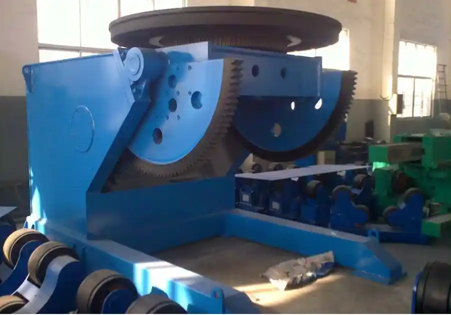
| Welding positioner | Rotates and tilts the vessel or subassembly | Load, eccentric load path, tilt range |
| Welding rotator | Supports the cylindrical shell and rotates it for girth welds | Vessel diameter range and anti-creep control |
| Fit-up rotator | Aligns shell sections before welding | Fit-up accuracy and adjustable alignment |
| Control system | Coordinates motion, programs, and weld parameters | PLC/HMI, program memory, robot interface |
Positioners Must Carry the Real Weldment, Not Just Its Weight
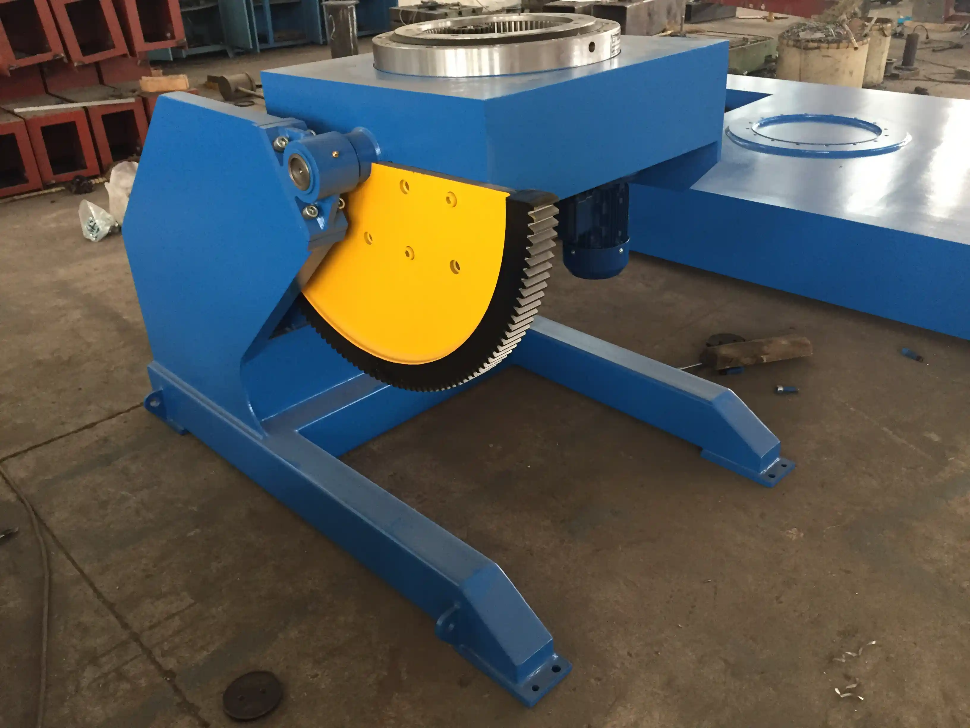
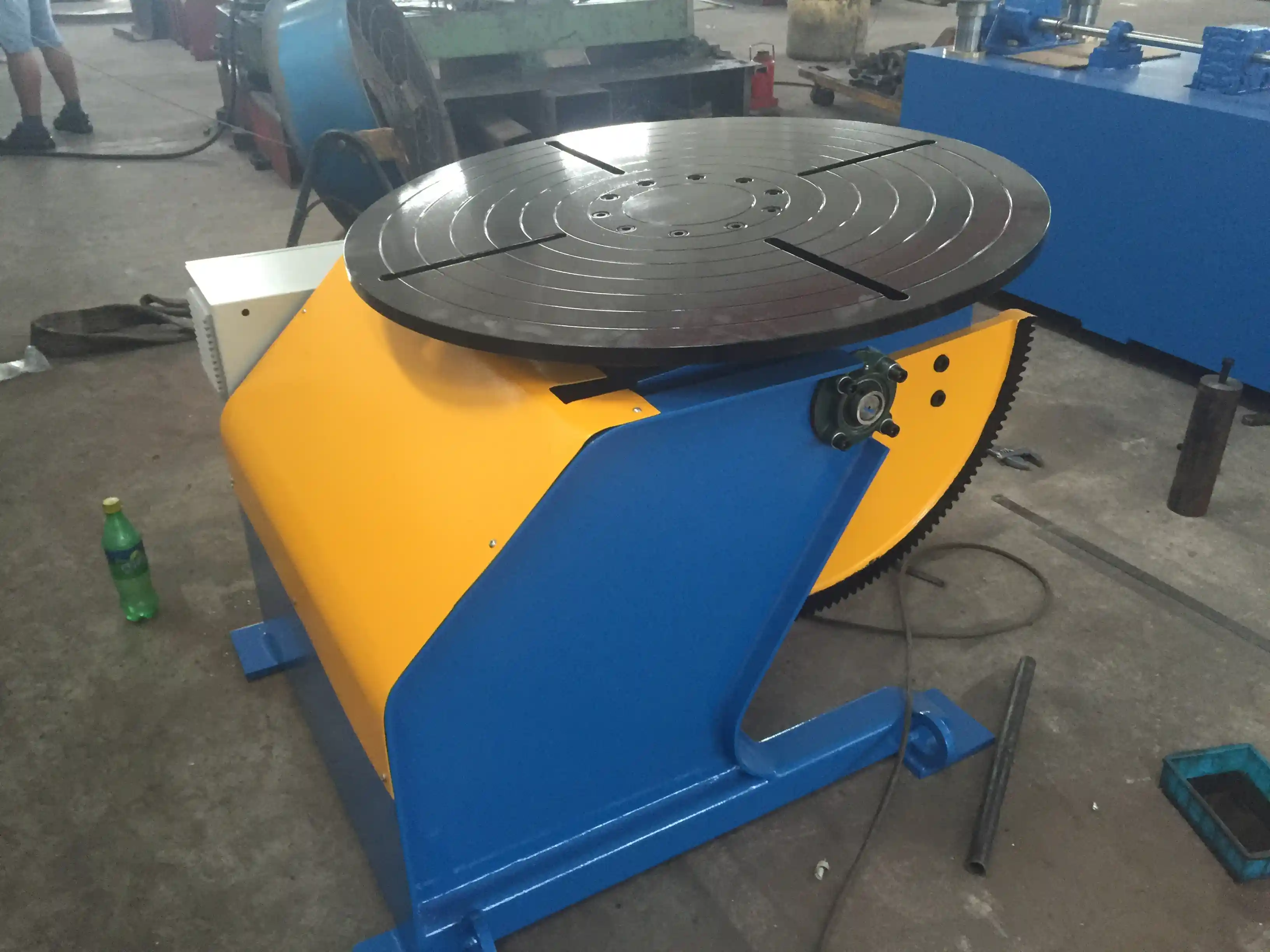
A load capacity number alone can mislead. The positioner has to handle the shell weight plus fixture weight at an offset from the table or support face. If the center of gravity moves outside the design envelope during tilt or rotation, the drive can overload even when the workpiece is below the rated tonnage. That is why the rated eccentric distance and center-of-gravity distance matter as much as the load figure. A 1-ton fixed height positioner may be rated for a maximum eccentric distance of 150 mm and a center-of-gravity distance of 200 mm. Exceeding either condition creates a different load case than the catalog rating assumes.
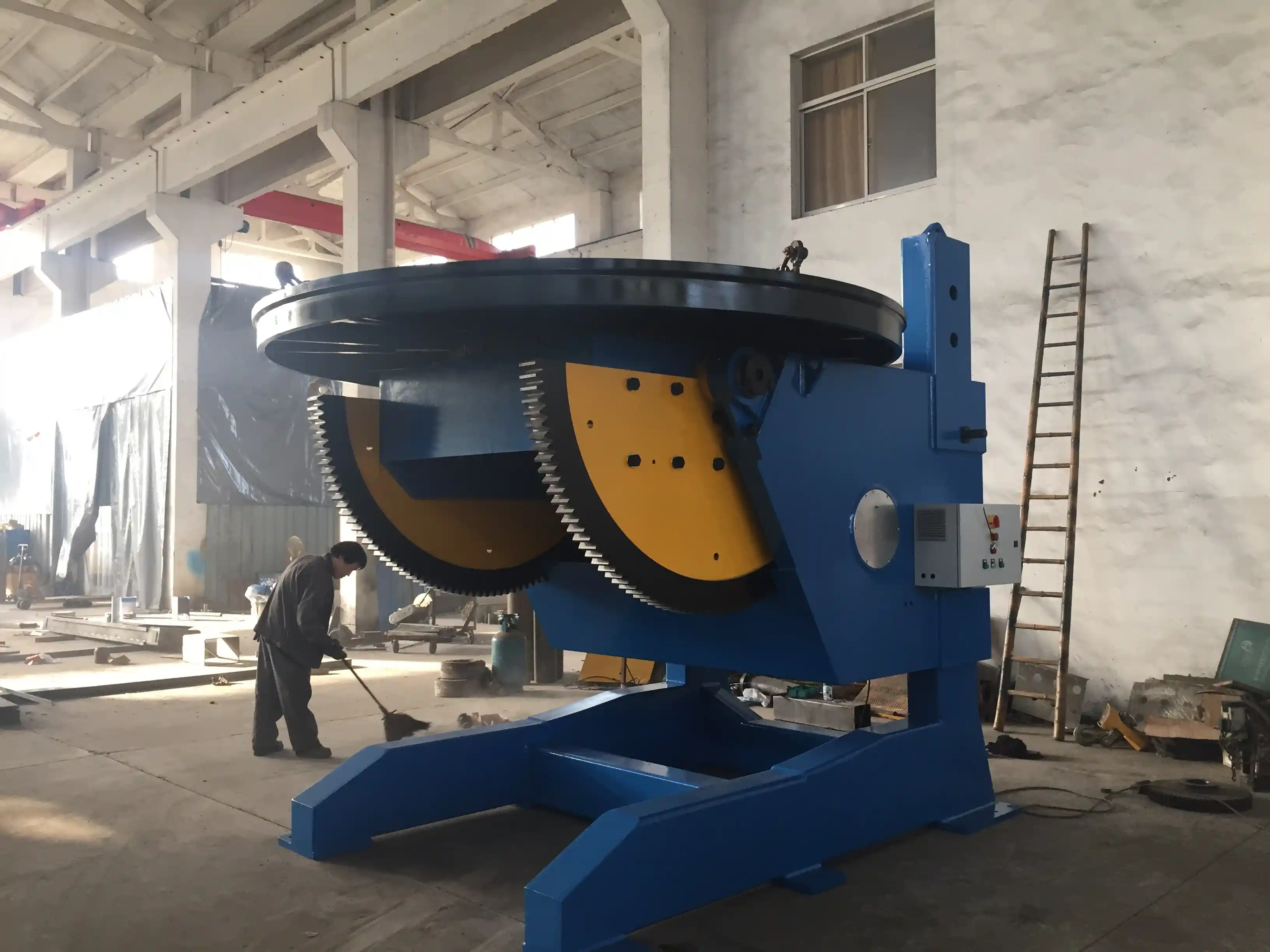
For heavier vessels, the issue shifts from motor power to overturning stability and backlash. A 5-ton model with a 1500 mm worktable may allow 0 to 120 degree turnover and 0 to 135 degree tilt through a cycloidal-worm reducer. The useful specification is whether that range can be reached without the workpiece, fixture, or operator entering an unstable position.
Pressure vessel seam welding depends on controlled rotation when the shell moves through flat, horizontal, and overhead positions. <Revolutionary Solution for Pressure Vessel Welding: Technical Analysis of 360-Degree Rotating Welding Positioners> covers how continuous rotation and tilting axes improve access for circumferential and nozzle welds.
Welding Manipulators Extend the Welder’s Reach Without Losing Alignment
A manipulator performs best when it keeps the welding head stable over a long travel path. The column supports the boom, the boom extends to the seam, and the carriage moves along the seam at a controlled rate. If the guideway or reducer has excessive clearance, the torch can oscillate or drift, which matters on long seams. Precision linear guideways and low-backlash reducers help maintain positioning accuracy. A manipulator with 8000 mm horizontal travel and 8000 mm vertical travel can cover large vessel seams, provided the rail foundation is level and the boom deflection remains within the stated accuracy.
WUXI ABK Machinery Co., Ltd. uses a box-beam structure, linear guideways, and stepless speed control in its welding manipulator line to hold positioning accuracy at ±0.1 mm/m. The choice of boom length and travel must still match the vessel layout, seam access, and the floor space available for column travel.
Rotators Keep Long Shells Round and Moving
Rotators support the vessel on roller frames while the welding head stays in place. The rollers must carry the shell without allowing it to walk axially during rotation. If the roller centers are not parallel, the shell creeps toward one end. Anti-creep mechanisms and adjustable roller spacing correct this. The vessel diameter range also matters. A 20-ton adjustable height rotator may accept vessel diameters from 500 mm to 4500 mm, so a shop with mixed vessel sizes needs to confirm both the smallest and largest diameter can be supported.
Large cylindrical sections in pressure vessel fabrication share the same rotational positioning requirements as wind tower shells. The support must carry the full shell weight, maintain alignment, and rotate at welding speed without axial drift.
Shell rotation supports the girth weld, but it only works when the roller system matches the vessel diameter and weight. <Innovative Applications of 10-Ton CNC Welding Rotators in Pressure Vessel Manufacturing> covers how CNC-controlled rotators handle vessel positioning and improve consistency in pressure vessel work.
Fit-up rotators go one step earlier in the sequence. They align two shell sections before welding and can hold them while the root pass is placed. The better the fit-up, the less the automation system must compensate later. A fit-up system may include hydraulic alignment carriages and track mounting for large diameters, which helps keep the joint gap and alignment stable before the automatic welding pass begins.
Controls Turn Motion Into a Qualified Process
Automated motion is only half of the cell. The controller must sequence rotation, travel, arc start, gas flow, and parameter changes. Modern positioners often use PLC and HMI touchscreen control with preset programs. Some fixed height positioners store 100 or more welding programs, and multi-axis positioners can accept robot interfaces from ABB, KUKA, FANUC, or Yaskawa. That does not make the weld qualified by itself. Weld procedure qualification, operator training, and inspection still determine whether the system can produce code-compliant work.
Process requirements also narrow the equipment choice. Submerged arc welding favors stable travel and flux recovery. GMAW and FCAW may benefit from seam tracking. GTAW may require a lower speed range and precise arc control. The control system should preserve the selected parameters and provide enough input and output capacity for the torch, wire feeder, oscillation, and safety interlocks.
Pressure vessel work is normally controlled by the construction code, such as ASME BPVC Section VIII, with welding qualification under the applicable code rules, commonly ASME Section IX. An automated system supports code compliance through repeatability and record retention, but the buyer should confirm the qualification and inspection plan rather than treating automation as approval.
Specifying the Right System for Fit-Up, Motion, and Verification
Before choosing equipment, define the worst-case joint and not the average shell. Ask whether the vessel will be rotated while the manipulator travels, or whether the torch will move along a stationary shell. Confirm the maximum shell diameter, shell length, wall thickness, and the position of nozzles or attachments that limit rotation. Then convert those values into engineering requirements: load, eccentricity, diameter range, boom reach, travel speed, rotation speed, and control functions.
| Requirement | What to verify | Why it affects cost and risk |
|---|---|---|
| Maximum weldment weight | Vessel plus fixture, not bare shell | Overturning and drive sizing |
| Eccentric loading | Center of gravity distance and offset at tilt | Backlash, stability, motor torque |
| Diameter range | Smallest and largest vessel | Roller spacing and height adjustment |
| Seam access | Longitudinal, girth, nozzle, internal | Manipulator boom length and positioner axes |
| Welding process | SAW, GMAW, FCAW, GTAW | Carriage speed, shielding, flux handling |
| Records | Procedure and inspection data | PLC/HMI, program storage, traceability |
A practical evaluation includes a trial with the actual vessel or a representative mock-up. Confirm that the shell can rotate through the full required range without the table or rollers approaching a limit, that the seam tracker can follow the joint, and that travel speed remains stable under load. Fixed-height positioners are useful when the vessel family is consistent and the shop layout does not require frequent height changes. Adjustable-height equipment becomes more valuable when the same cell must handle several vessel diameters.
Fixed-height positioners are useful when the vessel family is consistent and the shop layout does not require frequent height changes. <Exceptional Application Value: How Fixed-Height Welding Positioners Drive Advancements in Offshore and Shipbuilding Manufacturing> covers how fixed-height designs reduce complexity and support heavy cylindrical work in demanding manufacturing settings.
Start With a Joint-Specific Automation Review
Build the specification around the actual joint load, vessel diameter range, and weld code requirements. Send your vessel diameter, maximum shell and fixture weight, seam types, and welding process to WUXI ABK Machinery Co., Ltd., and the engineering team can help you compare manipulator, positioner, and rotator configurations for your shop. Contact Zhang Jian at jay@weldc.com or call +86-510-83555592.
FAQ
Do I need both a welding manipulator and a positioner for pressure vessels?
In most pressure vessel shops, yes. The manipulator gives controlled torch travel along the seam, and the positioner rotates or tilts the vessel for circumferential joints. A small shop producing only smaller pressure vessels may use a turntable or positioner alone, but long shell seams and heavy sections usually require both systems working together.
What load capacity should I specify for a positioner?
Specify the vessel weight plus the fixture weight, not the bare shell weight. Also confirm the center-of-gravity distance and eccentric distance at the worst tilt position. A positioner can stall or become unstable even when the vessel is below the rated tonnage if the load acts too far from the design centerline.
Can automated welding replace welder qualification?
No. Automation improves repeatability and helps maintain travel speed, torch angle, and rotation, but the welding procedure still needs qualification, and the operator or technician still needs training. Code compliance depends on the procedure, inspection, and records, not on automation by itself.
How do I prevent the shell from walking on rotators?
Start with roller alignment and confirm that the vessel diameter matches the rotator range. Use anti-creep mechanisms or adjustable roller spacing when available, and test at full load and welding speed. If the shell walks during rotation, stop and correct the roller centerline before continuing.
If you’re interested, check out these related articles:
Exceptional Application Value: How Fixed-Height Welding Positioners Drive Advancements in Offshore and Shipbuilding Manufacturing (Part 2)
Improving Quality and Efficiency in Tank and Pressure Vessel Manufacturing: The Core Application Value of Positioners
Improving Quality and Efficiency in Wind Power Manufacturing: The Key Role of Positioners in Tower Section Girth Welding
Mastering Heavy Manufacturing: How Climbing Roller Stands Become the Cornerstone of Efficient Welding
Low Efficiency in Pipeline Group Welding: How Intelligent Roller Racks Increase Productivity by 50%
 English
 Español
 Français
 Deutsch
 Português
 Русский