
Wind tower manufacturing solutions succeed only when the cutting, fitting, rotating, positioning, and welding equipment are designed as one load path rather than as separate machines. A tower shell section is heavy, round, and relatively thin-walled, so small alignment errors quickly become weld defects, straightening work, and schedule pressure. The practical approach is to specify the production line around the largest shell diameter, the heaviest section weight, and the required output per shift before selecting individual positioners, rotators, and manipulators.
What Wind Tower Production Actually Demands
A wind tower line is not a collection of independent welding stations. It must move long cylindrical segments, heavy flanges, and door frames while keeping the weld path stable. The main design constraints are shell diameter, segment length, wall thickness, and the lifting method used to carry a completed section from rolling to welding. If the rotator cannot hold the shell round under its own weight, the girth seam opens or compresses during rotation. That produces uneven root gap, arc length variation, and weld repair later.
The line should therefore be defined from the rotational support upward. Load distribution, not only motor power, determines whether the equipment can maintain the required weld position. 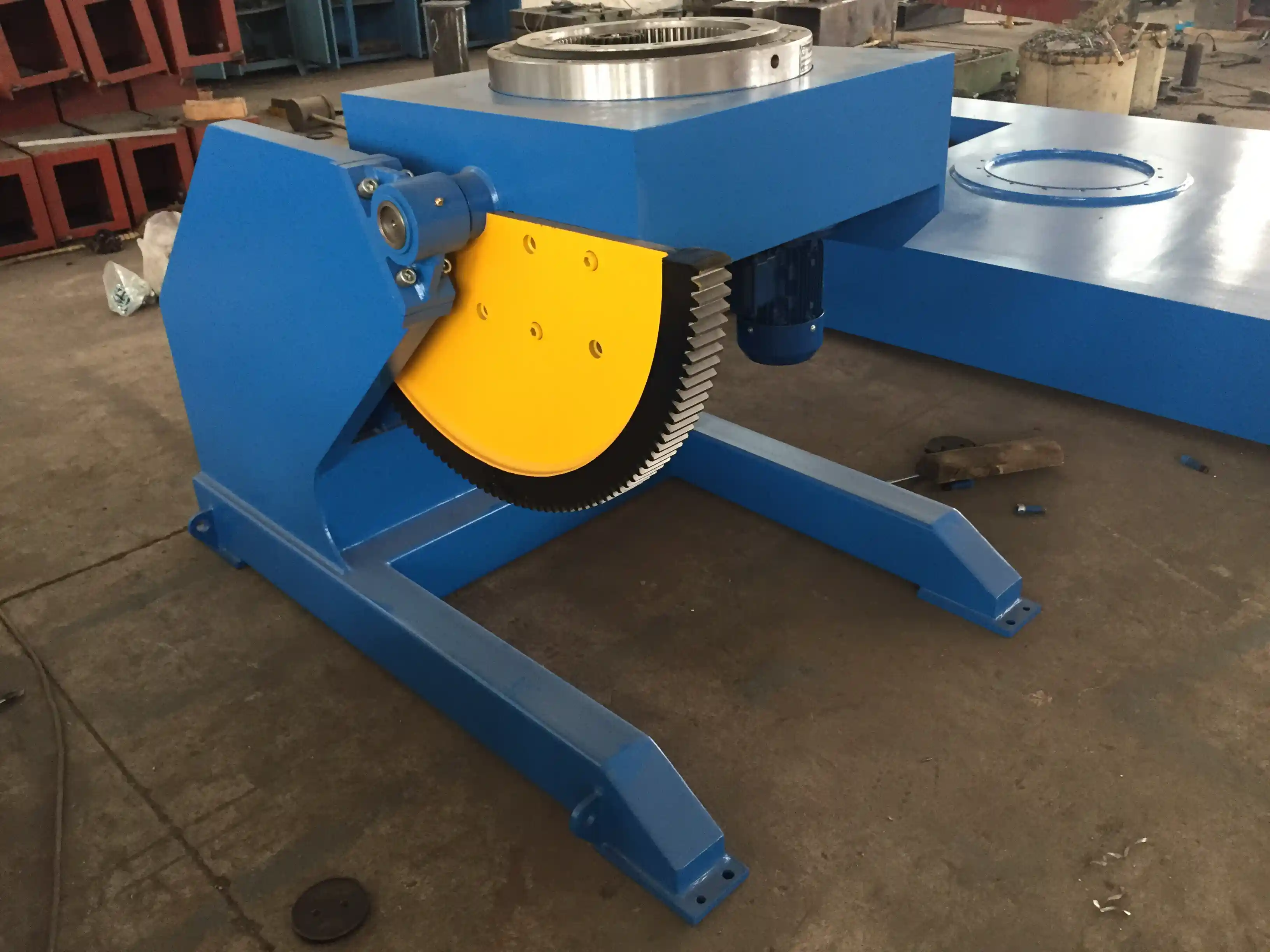
Fit-Up and Girth Welding Sequence
For tower sections, fit-up and girth welding are usually coupled. A typical sequence begins with tacking two shell cans on fit-up rotators, aligning the longitudinal seams to the approved offset, measuring root gap at several points, and confirming roundness before final welding. Once the joint is accepted, an adjustable-height rotator turns the assembly while a welding manipulator or submerged arc tractor keeps the torch on the seam.
The most common problem at this station is axial drift. As the heavy section rotates, one end can creep toward the drive rollers. An anti-creep roller or position feedback loop is more useful than a faster rotation speed because it prevents the torch from correcting sideways during the pass.
Girth welding quality depends on keeping the shell round and the seam orientation stable under full rotation. <Improving Quality and Efficiency in Wind Power Manufacturing: The Key Role of Positioners in Tower Section Girth Welding> covers the positioner functions that matter most for fit-up and weld access.
Choosing Rotating and Positioning Equipment
Three equipment groups do most of the work in a wind tower line: rotators, manipulators, and positioners. Rotators support the shell during girth welding. A height-adjustable rotator is preferred when the tower design changes frequently because it can match different section diameters without changing the foundation. A self-aligning design works best for long, flexible shells. A fixed-center design is acceptable only for a narrow product range.
The specification that matters first is not nominal tonnage alone. It is the vessel diameter range, the combined dynamic load, and the allowable creep during rotation. A 30 ton or 100 ton adjustable-height positioner may be selected only after the shell weight is calculated with the weldment center of gravity.
| Production stage | Equipment group | Key specification to confirm | Common failure mode |
|---|---|---|---|
| Shell can fit-up | Fit-up rotator | Diameter range, alignment accuracy, total load | Ovality and root gap drift |
| Girth welding | Adjustable-height rotator | Roller diameter, speed range, creep control | Axial drift and uneven rotation |
| Flange and circular seam welding | Welding positioner or turntable | Load capacity, eccentric distance, tilt range | Flange distortion and seam offset |
| Boom movement | Welding manipulator | Horizontal and vertical travel, boom stability | Arc length change and missed seam tracking |
| Long section lifting | Hydraulic lifting column or head-tail positioner | Lift height, synchronization, base distance | Uneven support and weld path shift |
| Recipe control | PLC and HMI | Preset programs, robot interface, feedback | Manual rework and long changeover |
Use this table as a screening tool, not as final acceptance proof. A photo or a nominal capacity figure confirms that the equipment is in the correct category. The actual design decision requires load curves, roller spacing, and the expected center of gravity for the heaviest tower section. A 5 ton rotator may be enough for a small top section, but the base section can exceed 100 tons and require a completely different support arrangement. 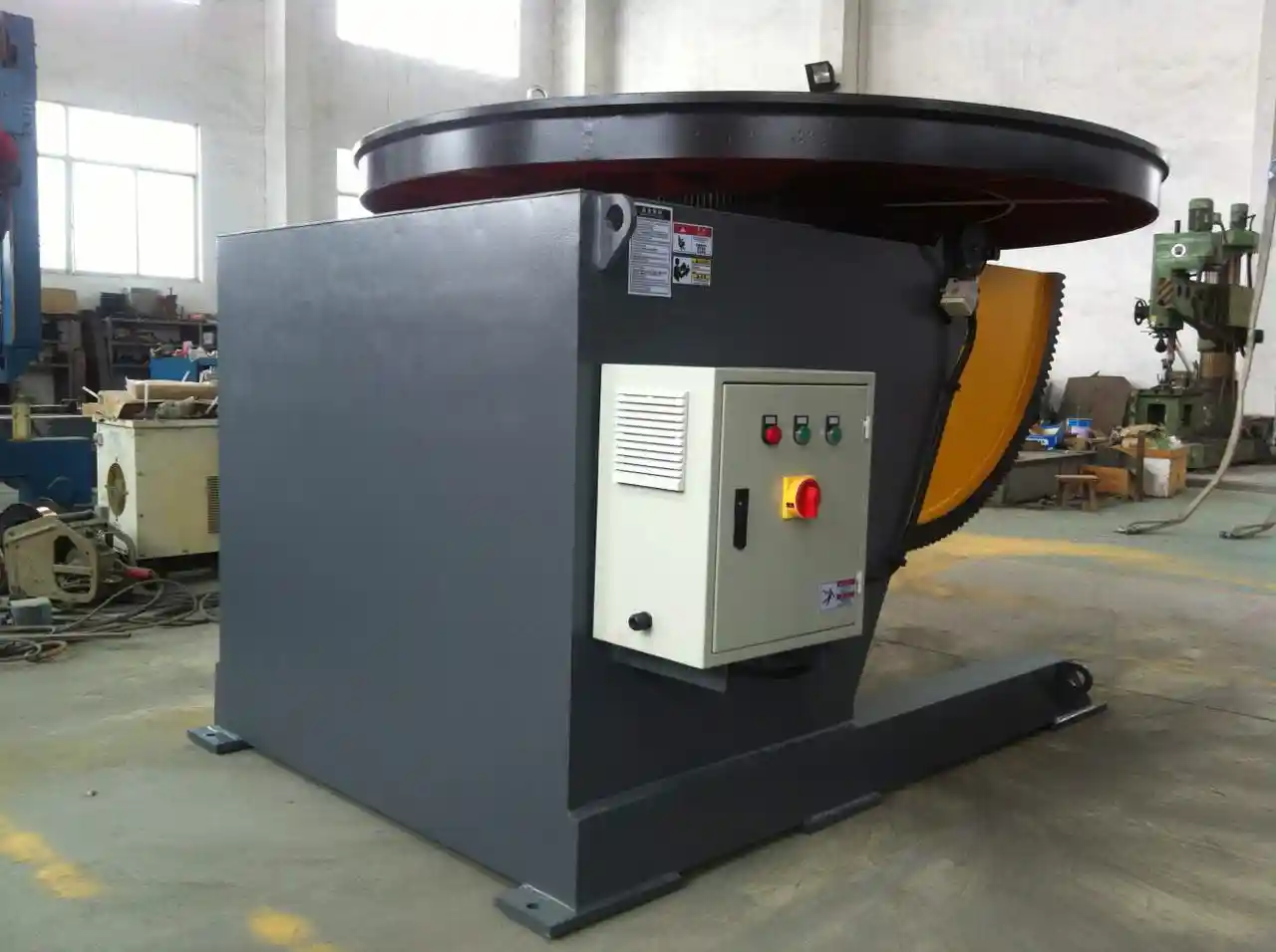
A coordinated line also has to keep the welding head above the seam without repeated manual repositioning. <Welding Manipulators for Wind Tower Fabrication: Revolutionizing Production Efficiency> covers how manipulator reach and travel affect wind tower production flow.
Reducing Distortion in Long Tower Shells
Longitudinal and circumferential welds pull the plate unevenly. In a tower shell, the two forces that cause most rework are radial shrinkage and axial bending after longitudinal seam welding. The practical control sequence is to weld the longitudinal seams first, round the cans before girth fit-up, and use a balanced welding sequence to spread heat input instead of concentrating it on one side.
If a can is already out of round before girth welding, no amount of positioner accuracy will produce a clean seam. A controlled rotator helps by holding the shell in the same round condition while the weld metal cools. A positioner that tilts and rotates under load also helps the operator avoid out-of-position welding on flanges and door frames, where heat input is easier to concentrate and distort.
Vertical weld quality is another issue, especially for tower sections welded in the vertical position or repositioned for flange work. The equipment must keep the section level and supported over the full lift range. When hydraulic lifting is out of sync, the weld path shifts and the root opening changes across the joint. This is why the selection review should compare lifting height, synchronization, and dynamic deflection rather than only stating a lifting capacity. 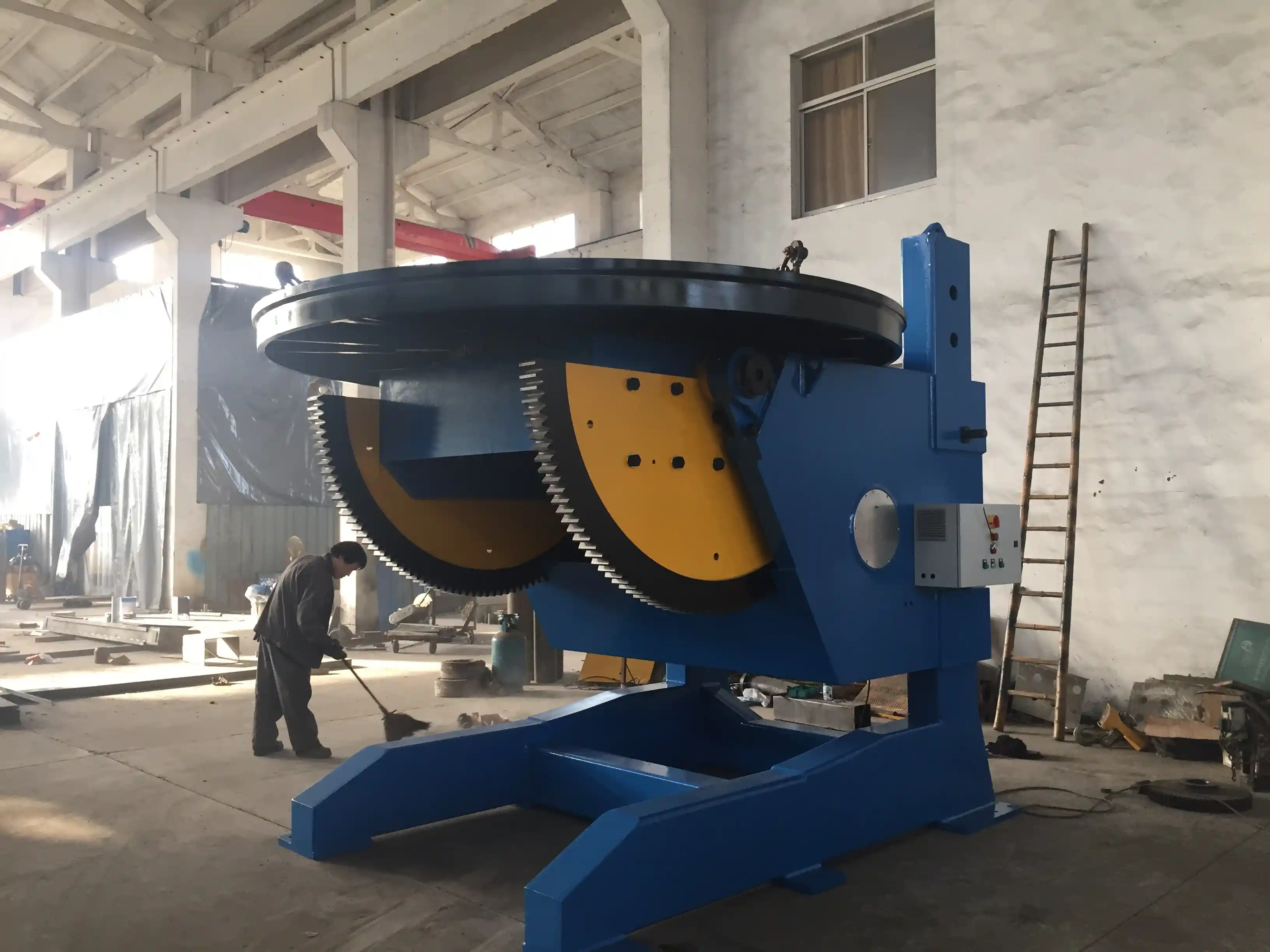
Vertical and flange welding problems often appear only after the section is lifted and turned under full load. <Wind Tower Welding Challenges: How Advanced Hydraulic Lifting Systems Boost Production by 40%> covers hydraulic lifting and alignment improvements for wind tower production.
Capacity Planning for Different Tower Designs
Capacity planning starts with three numbers: the heaviest section weight, the longest section length, and the required completed sections per day. These are design inputs, not marketing estimates. The line layout follows the material flow from plate cutting and rolling to fit-up, welding, flange attachment, and final inspection.
A high-volume factory may justify dedicated stations for each operation. A project-based fabricator may need flexible equipment that can handle both tower sections and pressure vessel components. The more important commercial decision is whether the line should be optimized for one tower platform or for a range of diameters and wall thicknesses. A WUXI ABK line specification normally starts with the maximum shell diameter and segment weight, then works backward through rotator capacity, manipulator reach, and lifting height.
For a typical onshore tower, base sections are the constraint. They are shorter, heavier, and thicker than the top sections. An adjustable-height rotator rated for the base section can still weld the lighter top section, but it may run at a lower utilization rate. The correct comparison is not purchase price per station. It is the cost of a mismatched support system, including rework, crane waiting time, and lost output when a section cannot be turned safely. Model parameters such as a manipulator with 8000 mm horizontal travel and 8000 mm vertical travel should be matched to the tallest weld joint rather than to the longest shell. 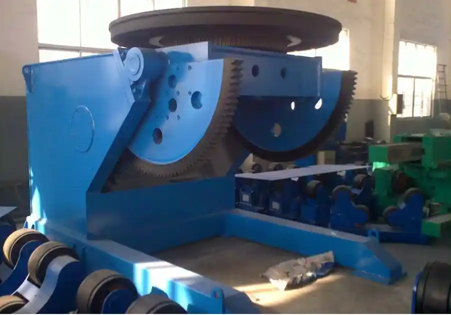
Building a Reliable Quality Check Loop
A complete wind tower line includes more than welding torches. It needs a repeatable check after each major step. After fit-up, measure root gap in at least four positions around the joint. After longitudinal welding, check roundness at the ends and mid-length. After girth welding, verify seam offset and visual surface condition before the section moves to the next station.
The equipment plan should leave enough floor space and lifting path for these checks, not only for welding cycle time. Automated data collection is useful only when it records the dimensions that drive acceptance, such as measured root gap and section ovality, rather than simply counting completed cycles. 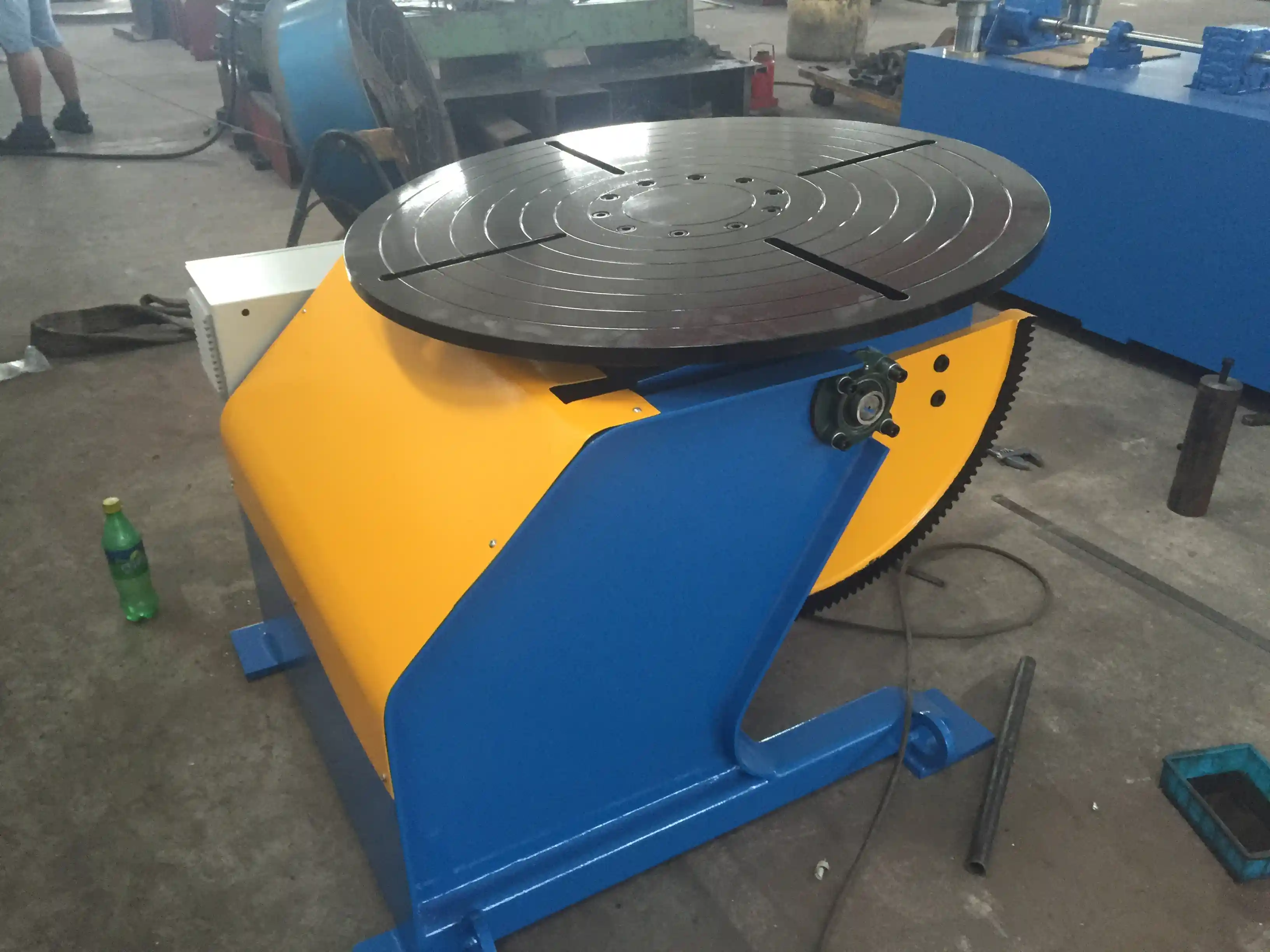
The line should also be easy to audit. Every preset program should identify the section type, material grade, welding procedure, and acceptable limits. When a weld defect appears, the review should be able to separate a process issue from an equipment issue quickly. This is easier when the rotator and positioner controls record speed, load, and alarm history at each station. It is harder when each machine has a different interface and no common recipe structure.
What to Send for a Wind Tower Line Specification
If you are planning a wind tower manufacturing line, send the largest shell diameter, maximum segment weight and length, steel grade and plate thickness, welding process, required output per shift, and available crane capacity. Those inputs are enough to compare rotator, positioner, and manipulator configurations without guessing at the heaviest section.
Contact WUXI ABK Machinery Co., Ltd at jay@weldc.com or call +86-13815101750.
FAQ
What equipment is essential for a wind tower production line?
A practical minimum includes plate handling and rolling, fit-up rotators, adjustable-height welding rotators, a welding manipulator or submerged arc system for girth seams, and a positioner or turntable for flanges and door frames. The exact set depends on the tower diameter, section weight, and output target.
How do I choose between a welding rotator and a welding positioner?
Use a rotator when the main operation is rotating a long cylindrical shell for longitudinal or girth welding. Use a positioner when the workpiece must tilt or turn for flange, door frame, or circular seam access. Many wind tower lines need both because the shell body and the flange require different motion control.
What is the most common source of girth weld defects?
In tower section welding, the usual source is not power or speed. It is poor fit-up and axial drift. If the shell is out of round or creeps during rotation, the root gap and arc length change during the pass. That produces inconsistent penetration and extra repair work.
How should I plan capacity for different tower models?
Plan around the heaviest base section first. Then check whether the same rotator and manipulator can handle the lightest top section without excessive idle time or setup changes. If the diameter or weight range is too wide, a flexible line with adjustable-height equipment is usually more practical than forcing one setup to cover every section.
If you’re interested, check out these related articles:
Excessive Misalignment in Pipeline Welding: Wuxi ABK Welding Turntable Precision Positioning Solution
Tired of Complex Welding Challenges? How a 3-Axis Positioner Can Boost Productivity by 70%
Exceptional Application Value: How Fixed-Height Welding Positioners Drive Advancements in Offshore and Shipbuilding Manufacturing (Part 2)
Core Pain Points and High-Precision Solutions of Welding Positioners in the Wind Power and Shipbuilding Industries: Comprehensive Technical Analysis
 English
 Español
 Français
 Deutsch
 Português
 Русский