A compact integrated production cell is not a lean-manufacturing diagram hung on a meeting-room wall. It is a deliberate arrangement of welding and cutting equipment that puts two or three sequential operations within arm’s reach of one operator — and the difference it makes to work-in-progress is immediate. In fabrication shops I have worked with, the typical pre-cell workflow routes a workpiece across four or five station-to-station moves before the first weld inspection happens. Each move adds forklift time, queue delay, and the risk of handling damage. A properly configured cell collapses those moves by clustering a CNC cutting table, a welding positioner, and a fit-up station into a single operator-managed sequence. The floor space argument gets attention, but the productivity gain comes from eliminating the idle hours between stations — hours that no ERP system can schedule away.
The Real Structure of a Compact Integrated Production Cell
Most descriptions of cell manufacturing start with a U-shaped layout and stop there. The shape is the least important part. What matters is that every station in the cell is matched to a common workpiece envelope — the maximum dimensions, weight, and orientation the part will require across all operations in the sequence. If the cell handles H-beam subassemblies up to 800 mm web height and 3 tons, then the cutting station, the tacking fixture, and the welding positioner must all accept that same envelope without requiring a crane move between steps.
A functioning cell has three layers. The equipment layer is the welding manipulator, the positioner, the cutting table — the machines that actually change the part. The handling layer is the roller conveyor, the jib crane, or the manual transfer cart that moves the workpiece from one station to the next without breaking the operator’s rhythm. The control layer is the pendant, the PLC interface, or the robotic controller that lets one person manage multiple machines without walking back and forth. Shops that skip the handling layer end up with a group of machines parked close together that still require a forklift between operations — that is not a cell, it is a rearranged floor plan.
Equipment within a cell does not need to be new. It does need to share compatible load ratings, work envelopes, and control voltages. We have integrated 10-year-old welding rotators with new CNC plasma tables in the same cell successfully because both could handle the same 2-ton, 1.5-meter diameter workpiece range. The integration problem is mechanical and dimensional first, electrical second.
Equipment Selection Principles for Cell Workflow
The most common mistake I see in cell design is selecting equipment the way you would for a standalone production line — buying the largest capacity available to cover every possible future job. In a cell, oversized equipment works against you. A 30-ton welding positioner in a cell that processes 2-ton fabrications consumes floor space, requires a heavier foundation, and rotates at a slower maximum speed than the work actually needs. The operator ends up waiting for the machine instead of the machine waiting for the operator.
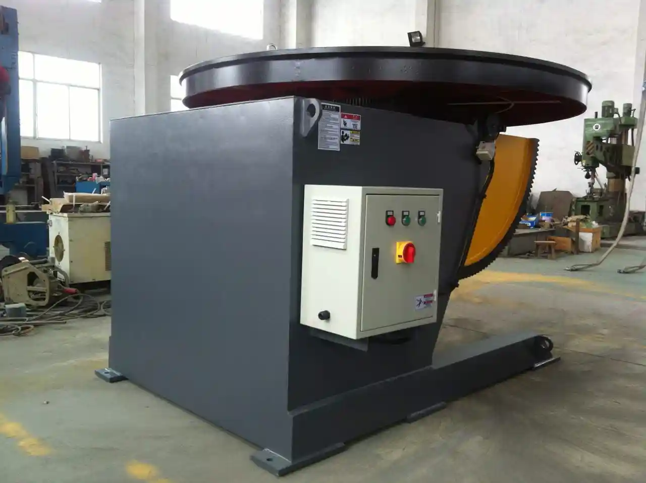
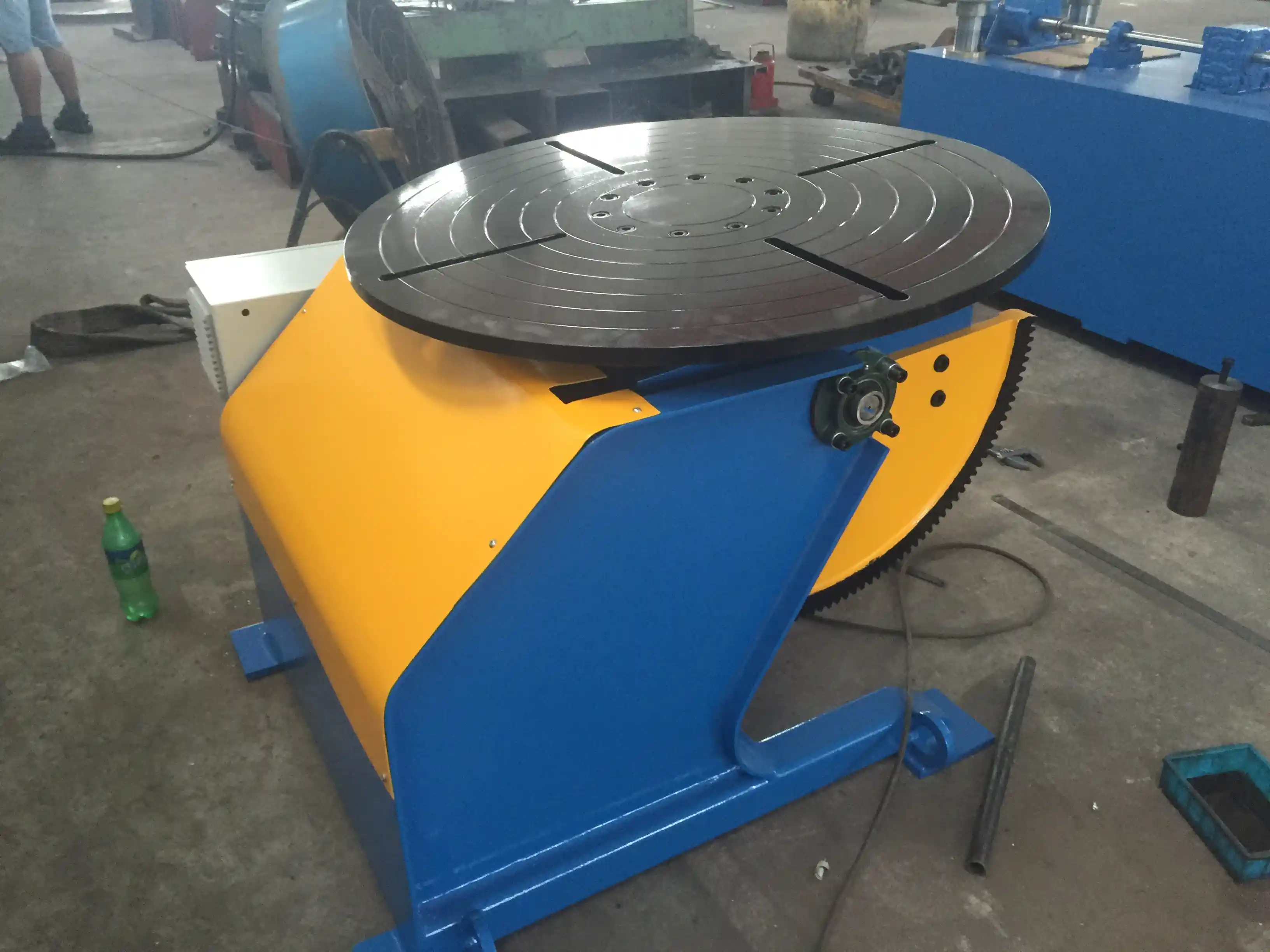
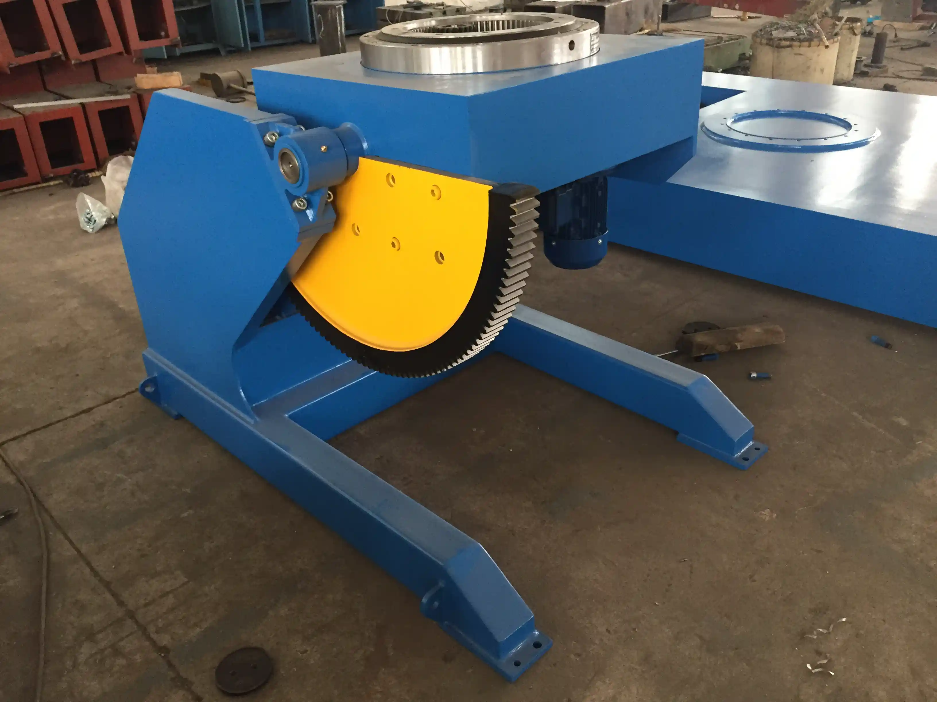
Match the positioner or manipulator to the actual workpiece weight and diameter range that will flow through the cell. For structural steel fabrications in the 1- to 3-ton range, a 3-axis welding positioner with a 3-ton load capacity and ±0.5 degree positioning accuracy is typically the right fit. The table diameter needs to accommodate the longest weldment dimension without overhang that would unbalance the rotation. For cylindrical work like pipe spools or small pressure vessel sections, a welding rotator with self-aligning rollers and a diameter range that covers the full product mix is more useful than a tilting positioner.
| Cell Function | Recommended Equipment | Key Specification to Match |
|---|---|---|
| Heavy structural welding | 3-axis positioner, 3–5 ton | Load capacity, table diameter |
| Cylindrical shell welding | Adjustable welding rotator | Roller diameter range, RPM |
| Plate cutting before welding | CNC plasma or flame table | Table width, material thickness |
| Fit-up and tacking | Fixed-height positioner with T-slots | Worktable diameter, clamping |
| Integrated robotic welding | 3-axis positioner with robot interface | Repeatability, control protocol |
Every machine in the cell should be operable from a single control zone. When the operator has to walk eight meters between a cutting table pendant and a positioner control box for every workpiece, the cell is a layout diagram, not a productivity tool. We specify pendant controls on long cables or wireless remotes for exactly this reason — the operator stays at the work point, and the machine control comes to the operator, not the reverse.
Layout Design for Single-Operator Production Cells
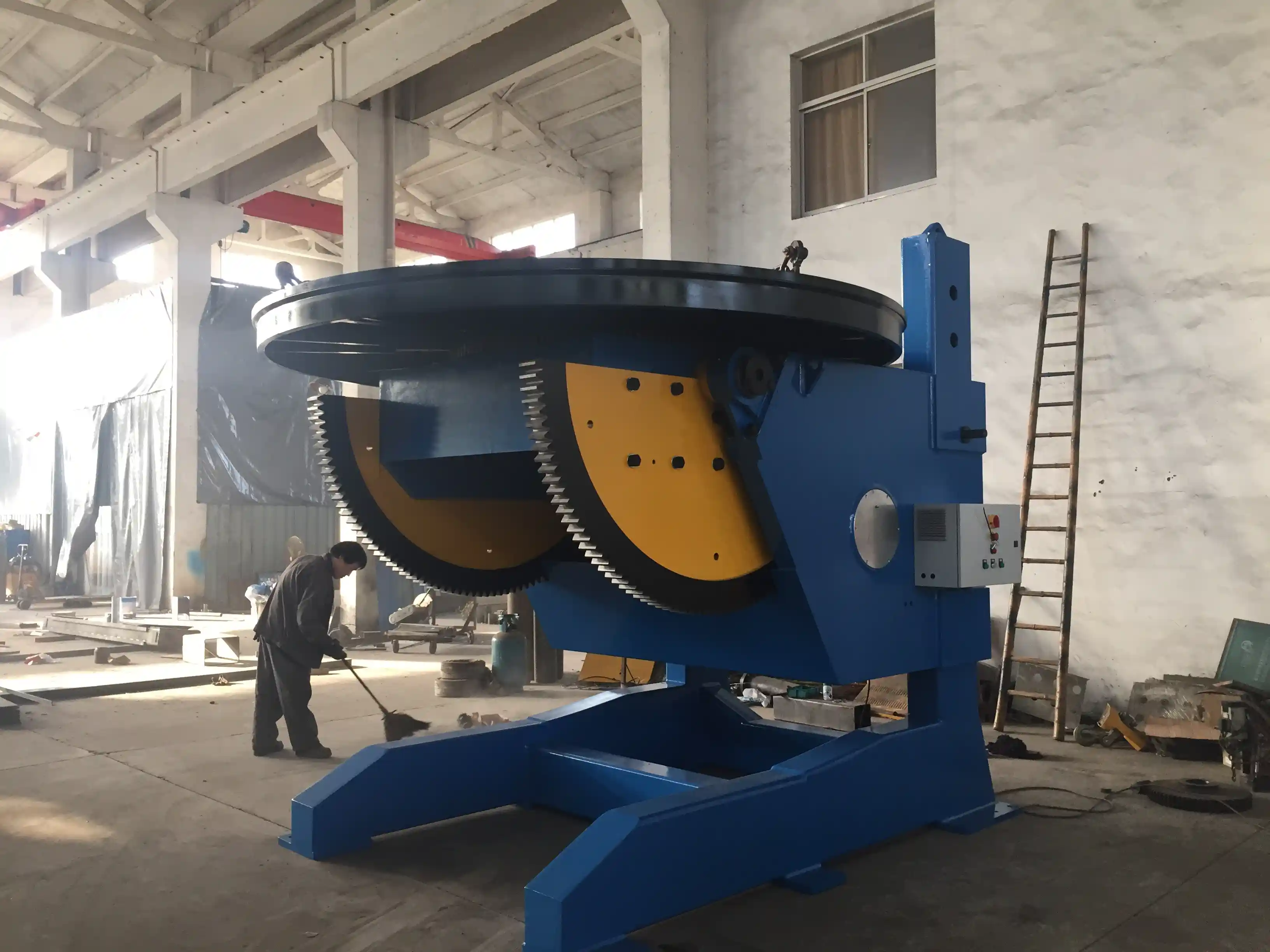
A cell layout that puts machines close together and calls it “compact” will fail the moment the first workpiece needs to be rotated or flipped. The spacing between a positioner and a welding manipulator must account for the workpiece at its maximum tilt angle — not its flat resting position. When a 2-meter-long beam is loaded onto a positioner and tilted 90 degrees for a circumferential weld, the tip of that beam sweeps through an arc that can collide with the column of a nearby manipulator if the spacing was calculated from the positioner’s static footprint alone.
I calculate cell spacing from the maximum radius the workpiece occupies during every operation in the sequence, plus 600 mm of operator access clearance. For a cell built around a 3-ton positioner handling parts up to 1.5 meters in length, the manipulator column should be positioned no closer than 2.2 meters from the positioner center. That sounds like a lot of space until you measure what a traditional batch-production layout requires for the same two machines with intermediate staging areas between them — typically three to four times the footprint.
The handling path through the cell should be a single loop with no backtracking. The workpiece enters at the cutting or prep station, moves to fit-up, then to the main welding positioner, and exits after inspection. If the operator has to carry or crane a part back to the cutting station for rework, the cell has a sequencing problem, not a layout problem. Addressing this at the design stage — before concrete is poured or machine bases are bolted down — is an order of magnitude cheaper than rearranging the cell after six months of production frustration.
If your operation involves varied workpiece sizes across different programs, it is worth confirming the cell’s maximum envelope early in the layout phase. A 3-axis positioner rated for 3 tons with a 1400 mm table diameter will define the upper limit of what the cell can process without breaking the single-operator workflow. Share your largest recurring workpiece dimensions and we can verify whether a standard cell configuration covers them — reach us at jay@weldc.com.
Integrating Welding Positioners and Rotators Into Fabrication Cells
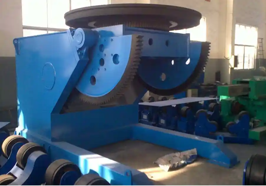
Welding positioners do the heavy lifting in a compact cell, but they are often treated as peripheral equipment rather than the cell’s central axis. I design cells around the positioner because the positioner determines workpiece orientation for the most time-consuming operation in the sequence — the welding itself. If the positioner cannot rotate at the speed the welding process demands, or if its tilt range does not give the welder access to all required joint positions, the cell’s cycle time is bottlenecked at the one station that should be the most productive.
The 3-axis positioners we manufacture for cell integration — ranging from 1-ton to 5-ton capacity — are built with THK linear guides and SEW reducers that maintain ±0.05 mm positioning accuracy under dynamic load. That level of precision matters in a cell because any position drift during rotation changes the weld joint alignment, and in a single-operator setup, there is no second person available to tap the workpiece back into position with a hammer while the welder waits.
For cells that handle cylindrical work — tanks, pipe sections, wind tower segments — a height-adjustable welding rotator paired with a column-and-boom manipulator creates a self-contained longitudinal and circumferential welding station. The rotator’s roller adjustment range must span the full diameter range of the product mix without requiring a tool change or manual shimming between jobs. Quick-change capability, meaning under ten minutes to switch from one workpiece diameter to another, is what separates a genuine production cell from a machine grouping.
Rotator selection for a cell follows a different priority than for a standalone line. In a standalone application, you size the rotator for the heaviest workpiece and accept that it will be underutilized on lighter jobs. In a cell, undersizing the rotator slightly — selecting a 10-ton model for work that peaks at 8 tons — keeps the roller diameter smaller, the motor power lower, and the overall machine footprint compact enough to maintain operator proximity to the adjacent stations.
Performance Changes After Switching to Compact Cell Production
The metric that shifts first is work-in-progress. Before a shop switches to a cell layout, it is normal to see a dozen or more workpieces staged between cutting and welding, waiting for the next operation. After the cell is running, that queue drops to one or two pieces — the one being worked on and the next one prepped at the entry station. The reduction is not subtle; it is visible from the mezzanine within the first week of operation.
Cycle time reduction comes from eliminating transport and queue time, not from making individual welds faster. A workpiece that previously spent 40 minutes of its total production time actually under the welding arc — and four hours sitting or being moved — now spends 40 minutes under the arc and perhaps 20 minutes in total cell dwell time. The welding parameters did not change. The space between the machines did.
Operator utilization increases, but that is not the same as operator workload. One operator managing a cell of three machines is not doing three people’s work; they are doing one person’s work without the waiting that used to fill their shift. The physical strain decreases because material handling — the heaviest labor in a fabrication shop — is reduced to the short transfer moves within the cell rather than full-shop transport. We have seen shops where the same operator who previously moved workpieces 60 meters per cycle now moves them four meters, and the difference in end-of-shift fatigue is measurable in reduced rework rates on the last hours of the shift.
Quality consistency improves for a reason that is easy to overlook. In a batch-production layout, a weld defect found at inspection might have been produced three hours earlier by an operator who has since completed forty other welds — and the root cause is lost in the time gap. In a cell, the operator inspects the workpiece at the exit station minutes after completing the weld. If there is a parameter drift or a fit-up issue, it is caught on the next piece, not the next shift.
Key Questions About Production Cell Implementation
Is cell manufacturing only suitable for high-volume production?
It is a persistent misconception that cells require mass production volumes to justify the setup. In practice, a compact cell works best in the medium-volume, medium-mix range — exactly where most job shops and project-based fabricators operate. If your shop produces between five and thirty similar fabrications per week, a cell will pay back the layout investment faster than a dedicated high-volume line would. The cell’s advantage is flexibility: switching from one workpiece type to another within the same envelope means changing the program and fixture, not rearranging the floor. For shops running fewer than five pieces per week of a given design, the cell configuration should use quick-change fixturing and casters under the lighter machines to permit reconfiguration within a shift.
How do you handle maintenance on equipment that is tightly grouped into a cell?
Maintenance access must be designed into the cell from the start, not improvised later. Each machine in the cell needs at least 800 mm of clear service access on the side where electrical panels, hydraulic connections, and lubrication points are located. This is separate from the operator access clearance used during production. We specify the service side of every positioner and manipulator on the layout drawing before the first machine is ordered. For cells with overhead cranes, the crane hook must be able to reach each machine’s heaviest removable component — typically the drive motor or reducer — without moving adjacent equipment. In cells where overhead access is limited, portable gantry frames or designated lift points on the machine bases solve the problem without requiring full disassembly of the cell.
Can existing welding positioners and cutting tables be reconfigured into a cell?
Most of the time, yes, with two qualifications. The machines must share a compatible workpiece envelope, and their control interfaces must be operable from a single operator position. A 15-year-old welding rotator with a manual pendant and a new CNC plasma table with a touchscreen controller can coexist in the same cell if the operator can reach both controls without walking more than two meters. The harder problem is usually the material handling path — if the existing machines were originally installed with forklift access from different aisles, reorienting them into a single loop may require moving electrical drops and foundation anchors.
What is the minimum floor space a practical fabrication cell actually needs?
A functional three-station cell — cutting, fit-up, and welding — for workpieces up to 2 tons and 2 meters in length can operate in roughly 60 to 80 square meters, depending on the specific equipment footprints. This assumes the operator works from the inside of a U-shaped arrangement with the three machines at the perimeter. Adding a fourth station for inspection or light assembly pushes the requirement to about 90 square meters. When shops tell me they cannot fit a cell into their existing floor plan, the issue is almost never total square footage — it is that the available space is fragmented by aisles, column lines, or storage racks that were never intended to support a continuous workflow. In those cases, relocating non-production storage is the first step, and it often frees more space than the cell requires. If your existing floor plan creates challenges that a standard cell layout cannot accommodate, share your current shop drawing and we will identify the reconfiguration options — contact me at jay@weldc.com or call +86-13815101750.
If you’re interested, check out these related articles:
Revolutionary Solution for Pressure Vessel Welding: Technical Analysis of 360-Degree Rotating Welding Positioners
Wind Tower Welding Challenges: How Advanced Hydraulic Lifting Systems Boost Production by 40%
Improving Quality and Efficiency in Wind Power Manufacturing: The Key Role of Positioners in Tower Section Girth Welding