
Precision CNC cutting for aerospace parts is not one number. It is the combined result of four separate capabilities: how accurately the machine positions its cutting head, how clean the edge is when the cut finishes, how much heat the material absorbs, and how firmly the part is held while it separates from the blank. A shop that quotes a positioning accuracy figure has proved one of those four. Buyers who treat that figure as the whole answer approve a process they have not seen tested on their own material and thickness. This guide explains how each capability is specified, where each cutting process actually fits, and what to measure before releasing aerospace parts to a supplier.
What Precision Actually Means in Aerospace CNC Cutting
Machine positioning accuracy and repeatability are defined test results. ISO 230-2:2014 describes how the accuracy and repeatability of positioning of numerically controlled axes are determined [1]. That value belongs to the machine under the test setup and environment used, and it does not describe the tolerance on a finished part. The cut itself adds kerf width, edge angularity and material movement on top of whatever the axes did.
Cut edge quality has its own vocabulary. ISO 9013:2017 classifies thermal cuts into geometric quality ranges and sets tolerances for perpendicularity, angularity and the profile of the cut face [2]. A purchase order that says “clean cut edge” cannot be inspected. One that names a quality range, an alloy and a thickness can be argued about with data.
Two further effects sit between the machine and the part. Kerf is the width of material removed, and it changes with process, alloy and thickness, so the compensation value programmed into the nest has to change with them. Taper is the difference in kerf width between the top and bottom face, and it is the usual reason a hole that measures correctly at the top fails a cylindricity check when inspected from the other side.
The boundary is worth stating plainly. A machine acceptance certificate, a demonstration cut in mild steel, or a brochure figure cannot establish capability on Ti-6Al-4V at the thickness you actually buy. Those records show that a machine was built and tested to a specification. Capability on your part has to be demonstrated on your part, in your thickness, with the consumables the supplier intends to run.
Choosing Between Laser, Waterjet, Plasma and Oxy-Fuel Cutting
The choice follows from three inputs rather than from a ranking: the alloy, the section thickness, and what happens to the edge after cutting.
| Process | Typical aerospace role | What it does well | What to plan for |
|---|---|---|---|
| Fiber laser | Thin sheet, skins, brackets, shims, clipped blanks | Narrow kerf, low heat input, fast on thin gauge | Thickness ceiling per alloy; dross on some grades; reflective surfaces need the right assist gas |
| Abrasive waterjet | Titanium, nickel alloys, thick plate, heat-sensitive parts | No heat affected zone, cuts most alloys, good for stacked blanks | Slower removal rate; taper control; abrasive supply and disposal cost |
| Plasma | Mid-thickness aluminum and steel structure, non-critical edges | Speed on mid-section material | Wider kerf and heat affected zone; edge angularity needs allowance |
| Oxy-fuel | Thick ferrous plate, weld preparations, heavy structural work | Capacity on heavy sections | Wide heat affected zone and low dimensional precision; not for non-ferrous alloys |
Laser cutting concentrates energy into a small spot and melts or vaporizes a narrow band of material, which is why kerf stays small and the surrounding metal stays cool on thin sections. Its limits appear as thickness rises, because the beam loses focus and the assist gas can no longer clear the molten material from the bottom of the cut.
Abrasive waterjet removes material mechanically. Because nothing is burned, there is no heat affected zone and no recast layer, which matters for titanium and for alloys that crack under thermal stress. The cost is speed, and the characteristic defect is taper, since the jet widens and loses energy as it travels through the plate.
Plasma and oxy-fuel remain production tools rather than precision tools in most aerospace work. They earn their place on thick structural items, on brackets where the edge is later machined, and on shop-built fixtures and tooling where a quality range tighter than the process can deliver would be wasted specification.
There is a fourth option that buyers often overlook: cut near net and machine the interface. If a bolted joint needs a tight fit, producing that surface on a milling machine from a roughly cut blank is frequently cheaper than forcing a cutting process past its economic limit.
How Aerospace Materials Respond to Different Cutting Methods
| Материал | Cutting behavior | What to inspect |
|---|---|---|
| Titanium alloys (Ti-6Al-4V sheet and plate to ASTM B265) | Reacts with oxygen at elevated temperature and forms a hard oxygen-enriched surface layer | Edge hardness and contamination; whether the affected layer must be removed before service |
| Precipitation-hardening aluminum (2024, 7075, 6061) | Conducts heat away quickly; dross and a narrow softened zone are common | Dross, recast, edge hardness and flatness after cutting |
| Precipitation-hardening stainless (15-5PH, 17-4PH) | Cuts cleanly by laser and waterjet with modest distortion | Recast layer, edge condition and dimensional stability |
| Nickel-base superalloys (for example Inconel 718) | Work hardens and resists chip formation; waterjet is slow but thermally clean | Taper, recast layer, microcracking near corners and tight radii |
Titanium deserves separate attention. When titanium is cut with a process that leaves it hot in the presence of oxygen, the surface absorbs oxygen and forms a hard, brittle layer usually called alpha case. That layer is not visible on a drawing and not detected by a dimensional check, but it initiates cracks, so most aerospace sequences remove it by machining or chemical milling before the part goes into service. The practical consequence is that a thermally cut titanium edge is an intermediate condition, not a finished surface, unless the process and the qualification data show otherwise.
Aluminum behaves in the opposite way. Because it conducts heat away from the cut so effectively, the heat affected zone stays narrow, but precipitation-hardened grades can soften within it. For a bracket loaded in fatigue, that local softening changes the assumption behind the design allowables, so the cut edge location relative to the highest stress region belongs in the process decision, not only in the drawing review.
Nickel alloys expose the tradeoff most clearly. Abrasive waterjet produces a metallurgically clean edge at low removal rates, and the taper becomes the controlling quality issue. Laser produces speed but leaves a recast layer in a material that is already difficult to inspect.
Programming and Nesting Errors That Reach the Part
Most cutting defects that survive to inspection were introduced in the program, not by the machine. Kerf compensation entered once for a whole nest, when the nest mixes two thicknesses, produces a part that is consistently oversize or undersize in a pattern that follows the sheet.
Lead-in and lead-out placement is the second common source. A lead-in that begins inside the finished contour leaves a witness mark on a visible face. Placing it in a scrap region costs a few millimetres of material and removes the defect entirely.
Common-line cutting between adjacent parts saves material and time, but on tight hole patterns it can change the roundness of the first hole in a row, because the cut on one side no longer has the same thermal or mechanical support as the other.
Toolpath order controls heat accumulation. Cutting every small hole in one small area before moving on lets heat build in that region and produces local distortion in thin sheet. Sequencing around the nest to balance heat input is a programming decision with a measurable result.
Tabs and micro-joints keep parts from tipping into the kerf, which is particularly relevant on small brackets and shims. A part that shifts after separation is a scrap part, and no downstream gauge will recover it.
Configuration control ties all of this together. AS9100D sets quality management requirements for aviation, space and defense organizations, and those requirements include control of production configuration and traceability of what was actually built [4]. In practice, that means the program revision released to the machine must match the drawing revision, and the nest report must identify which parts came from which sheet.
A useful check on all six points takes one afternoon: measure the first part and the last part produced from a single nested sheet, then compare. A drift between them is a heat, hold-down or consumable problem that a single sample part never reveals.
Where Positioning Accuracy Enters the Chain
A cut part becomes an assembly. When the bracket is located in a fixture and welded or machined, the locating error and the cut error add together, so a tolerance budget that assigns the entire allowance to the cutting machine will fail in assembly even when every individual cut part was in tolerance.
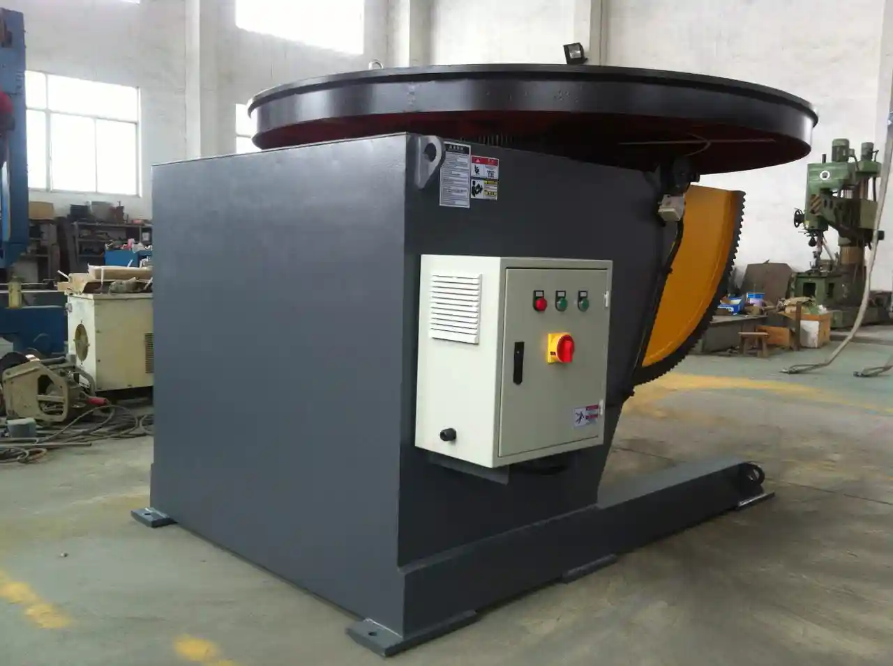
Positioning equipment for this stage is specified by axes, load capacity and repeatability rather than by a single accuracy figure. A three-axis positioner rotates, tilts and turns the workpiece so a joint can be presented flat, which converts a vertical or overhead weld into a comfortable position and stabilizes the weld pool.
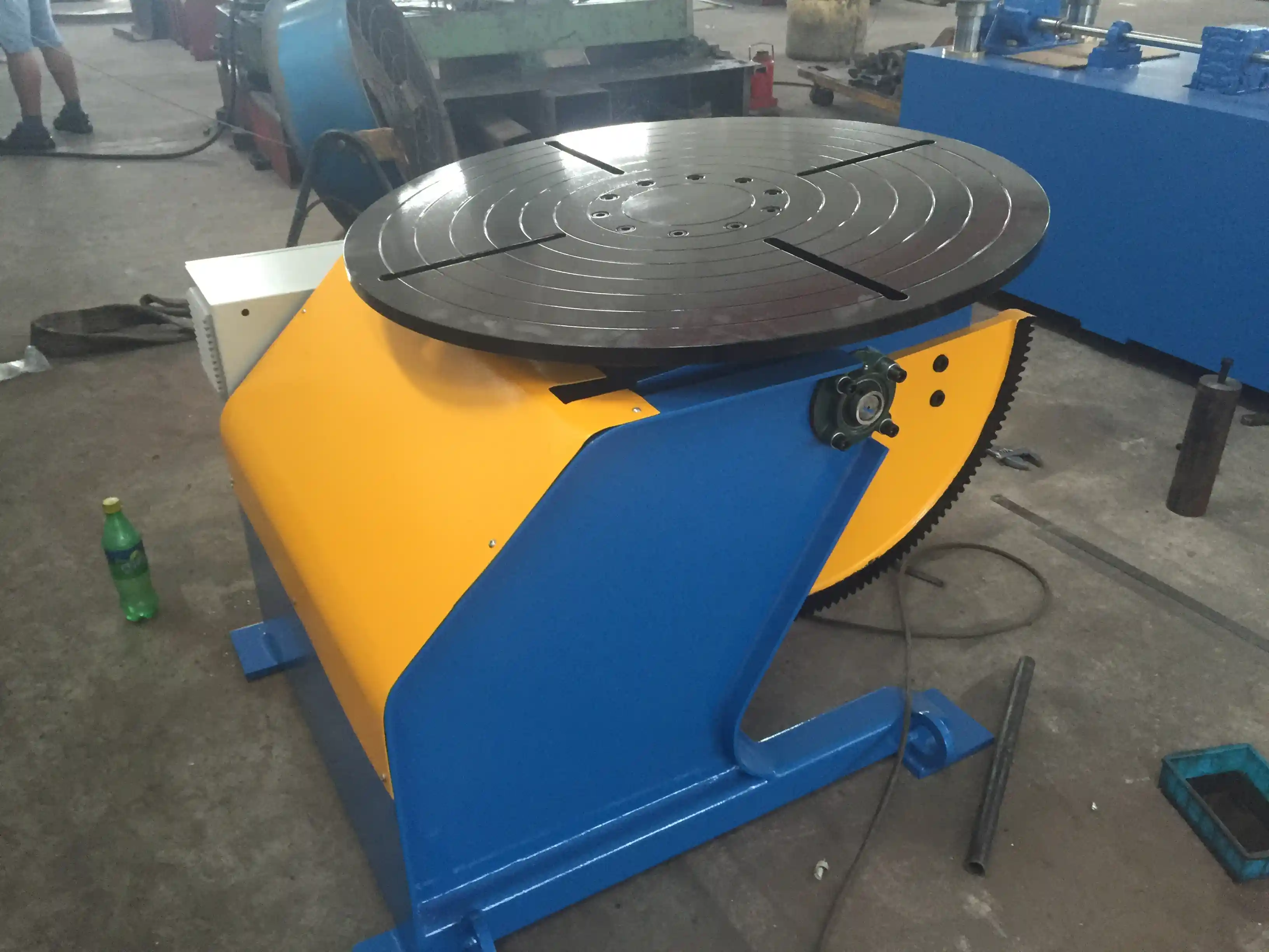
Work that needs the part turned and tilted between passes gains more from controlled indexing than from a faster torch. <Tired of Complex Welding Challenges? How a 3-Axis Positioner Can Boost Productivity by 70%> covers how a three-axis positioner reduces repositioning and setup time on repetitive joints.
Load capacity and overhang matter as much as nominal rating. A positioner carrying a long aerospace weldment at an offset centre of gravity sees a tilting moment far above the part weight, and a table rated for the mass alone will deflect or lose repeatability under it. The specification to request is the load at the eccentricity you will actually run.
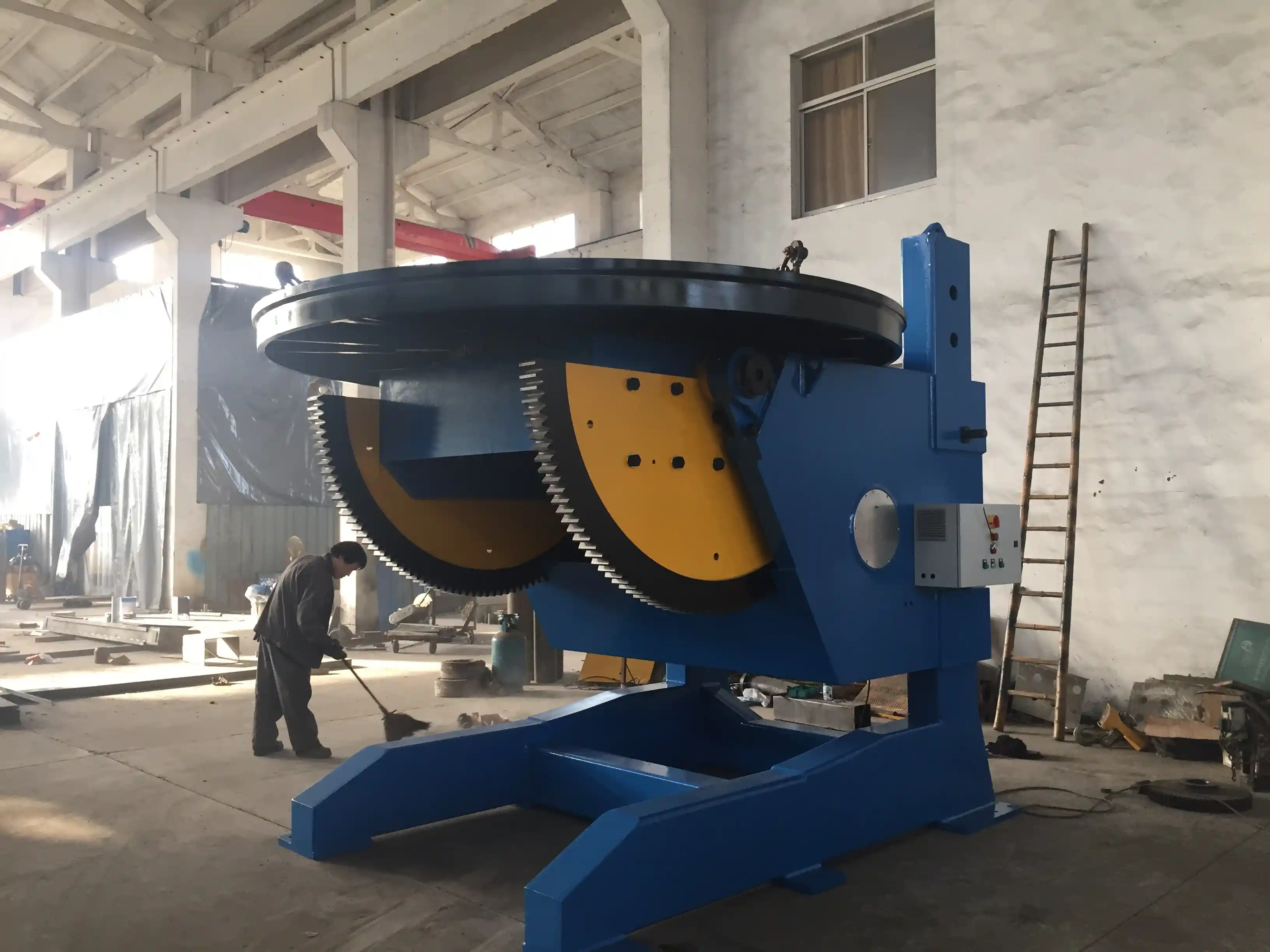
Repeatability is what makes a fixture worth building. If a positioner returns to the same angular position after every cycle, the operator can use fixed stops and preset programs instead of re-measuring between parts. If it drifts, every part needs an operator decision, and the fixture becomes the most expensive gauge in the cell.
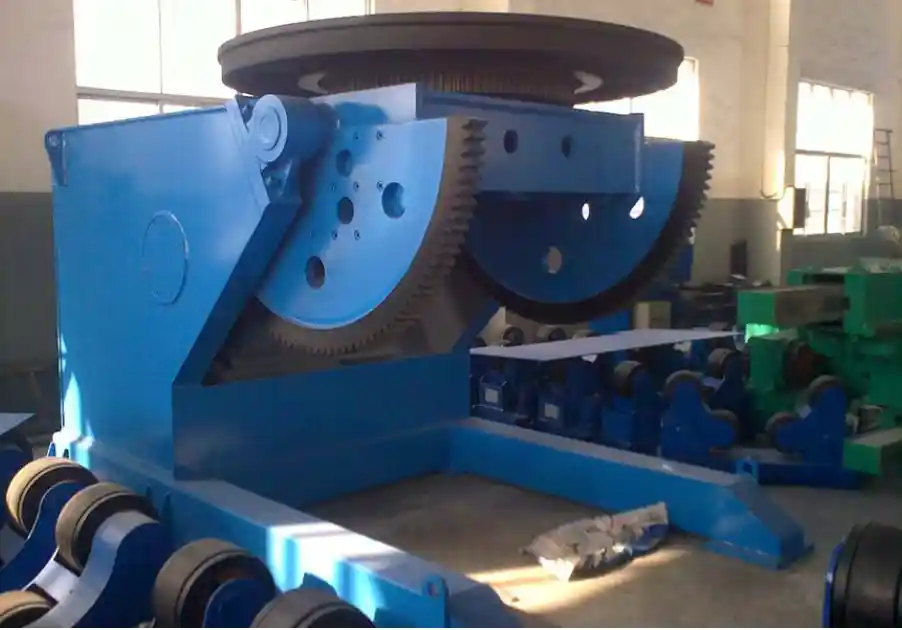
Repeatability is what justifies building a fixture in the first place. <Сварочный вращатель Прецизионная автоматизация для промышленного производства: Руководство эксперта по часто задаваемым вопросам> covers the positioning questions fabricators raise before specifying rotary handling equipment.
Large cylindrical assemblies, from aerospace pressure vessels to wind tower sections, are positioned by the same family of equipment, and the logic scales with them: rotation speed, load distribution across rollers, and the ability to hold a circumferential joint at a constant height.
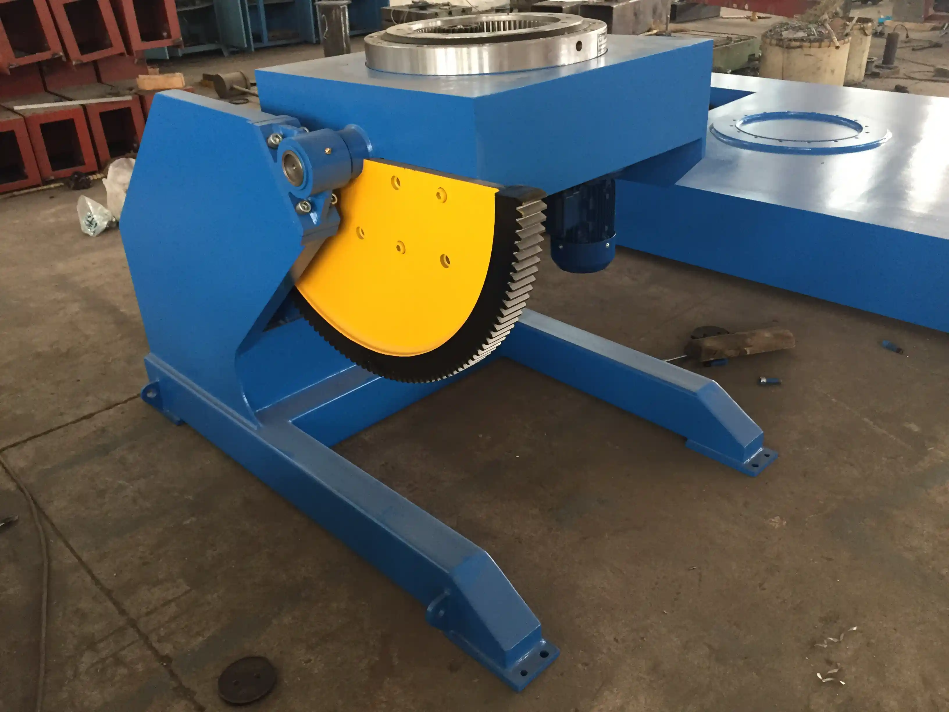
The boundary here is easy to lose. A precise positioner cannot correct a badly cut part. It reduces the error contribution of the holding stage, and nothing more. When a fit-up gap is too large, the audit trail usually leads back to the cut edge, the kerf compensation or the fixture datum, not to the positioner.
Qualifying a Cutting Process for Aerospace Work
- Define the acceptance basis before the first cut. Record the material specification and condition, the thickness range, the cut quality range, the dimensional tolerances, the edge condition requirement and whether a metallurgical check applies. For titanium sheet and plate, ASTM B265 gives the material basis on which everything else rests [3].
- Require a test cut on production material. Same alloy, same thickness, same temper, ideally from the same mill lot. A demonstration in mild steel says nothing about an alloy that reacts with oxygen.
- Measure the right characteristics. Dimensional accuracy, perpendicularity and angularity of the cut face, kerf width at top and bottom, dross, and the presence of recast or alpha case where the alloy is sensitive to it.
- Check capability across the run, not at one point. Measure the first part, the last part of the nest, and the first part after a restart or a consumable change.
- Confirm documentation and configuration control. Material certificates, program revision, machine calibration records and the flow-down of quality system requirements where the part is flight hardware [4].
- Re-qualify after any change. A new material lot, a new thickness, a different assist gas, a new nozzle or a different shift can all move the result outside the qualified window.
An accredited quality system shows that a supplier controls its processes and its records. It does not show that a particular cut holds a particular tolerance on a particular alloy. Only inspection data from that material and thickness does, which is why a certificate and a first article report answer two different questions and a buyer needs both.
Send the Part Drawing Before You Choose a Cutting Process
The fastest way to get a workable process recommendation is to send the details that constrain it: alloy and temper, thickness range, the tolerance that actually governs fit, the cut edge requirement, the downstream welding or machining step, and the inspection standard you work to. With that list, a supplier can say which process fits and which parts of the job need a test cut before anyone commits to a production run.
Wuxi ABK Machinery Co., Ltd builds CNC cutting machines and welding automation systems for heavy fabrication, and can review a drawing against process capability before quotation. Email jay@weldc.com, or call +86-510-83555592 or +86-13815101750, with the part drawing and the list above.
ЧАСТО ЗАДАВАЕМЫЕ ВОПРОСЫ
Is laser cutting accurate enough for aerospace parts?
For thin-gauge aluminum, stainless and shim stock, fiber laser holds tolerances and edge quality that satisfy many aerospace drawing requirements, and its low heat input limits distortion. The limit is thickness and alloy: titanium and nickel alloys at heavier sections usually need waterjet or a cut-then-machine sequence. “Laser is accurate” is not a specification. Name the alloy, the thickness and the cut quality range, then confirm with a test cut on that material.
Can abrasive waterjet hold tighter tolerances than laser?
Not automatically. Waterjet’s advantage is the absence of a heat affected zone and its ability to cut alloys that crack or react when heated. On thin sheet, laser often holds tighter dimensional control and a narrower kerf. On thick titanium or nickel alloy, waterjet is frequently chosen despite slower removal because the alternative is a metallurgical cleanup operation. The correct comparison uses your alloy and thickness, not a general ranking.
Does plasma cutting damage aerospace aluminum?
Plasma leaves a heat affected zone and a rougher edge than laser or waterjet, and in precipitation-hardened alloys that zone can soften locally. It does not make the part unusable. For brackets and structure where the cut edge is later machined or where the edge sits away from peak stress, plasma is a practical production choice. Where edge metallurgy governs fatigue life, specify the process and verification that match the design requirement.
What documentation should come with aerospace cut parts?
At minimum: material certificate with heat number and condition, the program revision used, machine calibration status, dimensional and cut quality inspection results, and any metallurgical check required for the alloy. Where quality system requirements flow down from the customer, records showing control of that configuration are part of the deliverable. Documentation shows what was intended and verified; it does not replace inspecting the parts against the drawing.
References
[1] ISO 230-2:2014, “Test code for machine tools — Part 2: Determination of accuracy and repeatability of positioning of numerically controlled axes,” ISO, 2014.
[2] ISO 9013:2017, “Thermal cutting — Classification of thermal cuts — Geometrical product specification and quality tolerances,” ISO, 2017.
[3] ASTM B265, “Standard Specification for Titanium and Titanium Alloy Strip, Sheet, and Plate,” ASTM International.
[4] SAE International, “AS9100D Quality Management Systems — Requirements for Aviation, Space and Defense Organizations,” SAE International, 2016.
Если вам интересно, ознакомьтесь со следующими статьями по этой теме:
Исключительная ценность применения: Как сварочные позиционеры с фиксированной высотой способствуют прогрессу в морском и судостроительном производстве
Сварочный вращатель Прецизионная автоматизация для промышленного производства: Руководство эксперта по часто задаваемым вопросам
Wuxi ABK Professional Welding Rotary Equipment: Precision Welding Solution for Pressure Vessel Manufacturing
Tired of Complex Welding Challenges? How a 3-Axis Positioner Can Boost Productivity by 70%
Революционное решение для сварки сосудов под давлением: Технический анализ вращающихся на 360 градусов сварочных позиционеров
 English
 Español
 Français
 Deutsch
 Português
 Русский