
CNC flame cutting speed charts give a useful starting point, but most published tables understate how much material type, plate condition, and machine setup change the number you can actually run. I have spent more than twenty years working with CNC flame cutting and welding automation, and the most common production problem I see is not the chart being wrong. It is the operator holding the chart speed without adjusting preheat, nozzle size, or torch height for the actual plate. The result is uneven kerf, slow pierce times, and cut edges that miss tolerance before welding. This guide breaks down cutting speeds by material type and thickness, then explains the four variables you must correct before you trust a chart.
The CNC Flame Cutting Speed Chart Drops Sharply With Thickness
Speed charts for CNC flame cutting are not linear. At 10 mm, cutting speed usually sits between 400 and 480 mm/min with a standard machine torch on clean low-carbon steel. At 50 mm, that value drops to about 170 to 210 mm/min. The curve flattens at thicker sections, but the thermal load, oxygen stream, and slag evacuation all change at once, so a small error in preheat or nozzle selection costs more at 80 mm than it does at 12 mm. If you compare tables from different machine builders, the values rarely differ by more than ten percent at a given thickness because the physical cut front limits the process. The bigger variation comes from machine condition and setup.
| Материал | Толщина | Typical Speed (mm/min) | Notes |
|---|---|---|---|
| Low-carbon steel | 10 mm | 400 to 480 | Standard machine torch, neutral preheat |
| Low-carbon steel | 20 mm | 300 to 360 | Keep torch height steady |
| Low-carbon steel | 30 mm | 240 to 290 | Preheat intensity rises sharply |
| Low-carbon steel | 50 mm | 170 to 210 | Watch top edge rounding and slag |
| Low-carbon steel | 100 mm | 100 to 140 | Slow pierce, evacuate slag before travel |
These values assume low-carbon steel, neutral preheat, a clean nozzle, steady torch height, and flat plate. They also assume the machine can hold travel accuracy while piercing. If the cut shows top edge rounding, deep drag lines, or heavy bottom slag, speed is only one of several adjustments. The real constraint is often torch height, nozzle condition, or plate flatness.
In practice I treat a speed chart as a starting value and validate it on an offcut. A correct cut at speed shows a slight backward lean in the drag lines, a square top edge, and light, easily removed slag. If the top edge is rounded or the bottom carries heavy oxide, the cut is not moving at the right condition, and the first check should be preheat and nozzle cleanliness rather than travel speed.
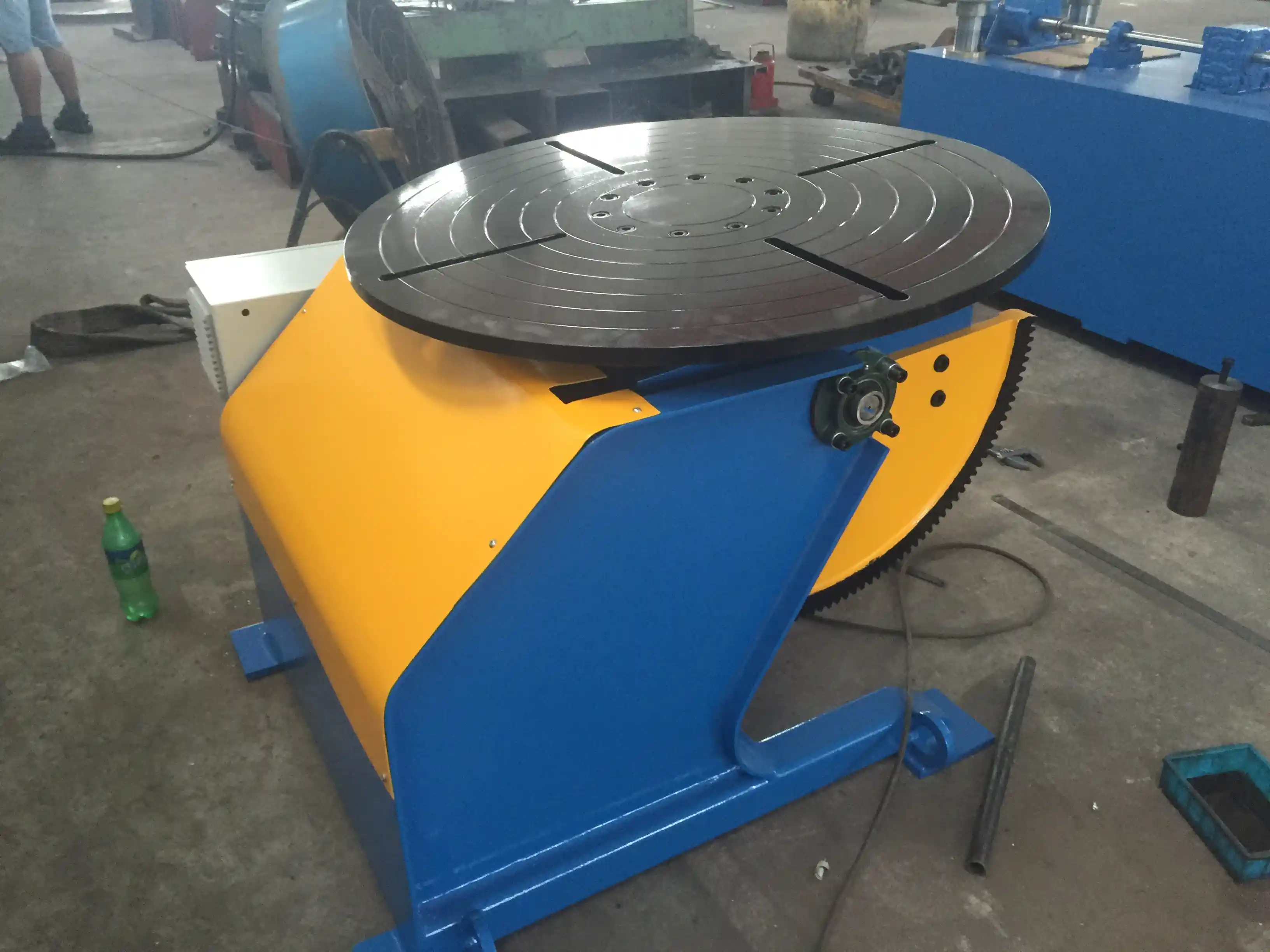
After plate is cut, the parts move to fit-up and welding. <Повышение качества и эффективности производства резервуаров и сосудов высокого давления: Основные возможности применения позиционеров> covers how controlled positioning holds vessel shell sections during weld-out, and why clean, square cut edges reduce fit-up time before a positioner reaches its full output rate.
Material Type Changes Preheat and Practical Speed
Many published speed tables fall apart when the steel grade changes. Mild steel cuts well with oxy-fuel flame cutting. Once the material carries more carbon or alloying elements such as chromium, molybdenum, or manganese, the oxide chemistry shifts and the reaction becomes less stable. High-carbon and low-alloy steels then need more preheat and often a lower travel speed than a mild steel chart suggests, not because the machine is slow but because the cut front is less regular.
Stainless steel and aluminum do not respond to standard oxy-fuel CNC flame cutting. The oxide layer blocks the oxygen reaction. These materials belong on plasma or laser equipment. If a shop mixes stainless and carbon steel work, the choice of cutting technology matters more than fine-tuning flame cutting speed.
That divide shows up in boiler, pressure vessel, and tank work. A516 carbon steel plate cuts close to mild steel numbers after the grade and preheat are confirmed. Quenched and tempered grades or normalized high-strength plate may demand slower speeds and controlled preheat so the cut edge does not harden enough to cause cracking later. With high-carbon plate, the area next to the cut can harden because the flame adds heat and the steel cools quickly. That hardened zone can crack when the part is welded or formed. For plate over 50 mm, many shops preheat to around 150 degrees Celsius or higher depending on grade before starting. The correct preheat comes from the steel specification, not from the speed chart.
Nozzle Size and Gas Flow Set the Usable Speed
The speed the chart lists is not set by the CNC control alone. It comes from a chain that starts at the torch nozzle. A nozzle with too small a bore or too little cutting oxygen pressure cannot keep the kerf clear, so the operator slows down to avoid losing the cut. A nozzle with too large a bore wastes gas and widens the kerf. The table only works when the nozzle matches the plate thickness.
Acetylene and LPG or natural gas preheat flames behave differently. Acetylene concentrates heat at a higher temperature close to the nozzle, which shortens pierce time on thinner sections. LPG and natural gas lower fuel cost but need a longer preheat cycle on thick plate. The main effect is on pierce time and cycle time, not on steady cutting speed. If the pierce is rushed on thick plate, the flame can climb the plate face and the chart speed becomes meaningless.
The cutting oxygen jet does most of the work in oxy-fuel flame cutting. Cutting oxygen pressure above the recommended range can produce a wider kerf and more top-edge melting without adding useful speed. Pressure that is too low is more dangerous because the cut may not penetrate and the machine drags. That is a common cause of operators running below the chart.
If the work centers on 40 mm and thicker steel, it is worth confirming cutting oxygen pressure and nozzle bore against the actual plate grades before committing to production settings. Send the material list to jay@weldmc.com and we can check the gas parameters.
Machine Rigidity Decides How Much of the Chart You Can Use
A speed chart assumes the cutting head holds the right height and moves through the programmed path without lag. On a light gantry or a machine with worn rails and gear rack, the torch may bounce or trail at higher speeds. The operator then drops speed below the chart to stop the cut from wandering. That is a stiffness limit, not a process failure.
CNC flame cutting machines with solid gantry structures, precision rack and pinion drives, and responsive servo motors hold acceleration through corners more consistently. Torch height control matters here because the rail and cutting table need to stay level. If the plate sits on a slatted table with poor support or the electronic height sensing is misadjusted, the nozzle dives or climbs during a cut. The chart speed gives good results only when the tool follows the plate surface.
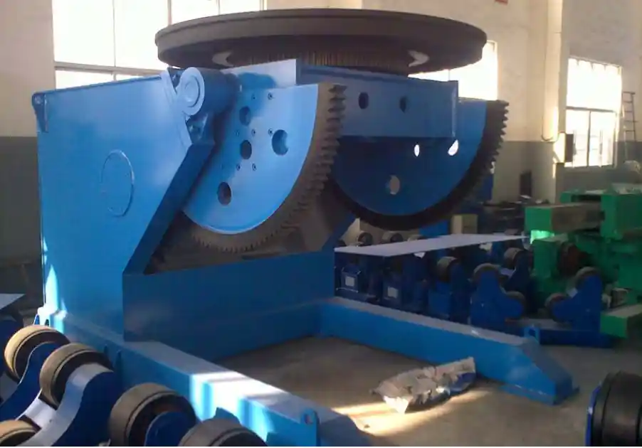
In heavy plate fabrication, the accuracy left by the cut determines how much time goes into the next station. <Чрезмерное смещение при сварке трубопроводов: решение для прецизионного позиционирования сварного поворотного стола от компании Wuxi ABK> covers how rotary positioning keeps pipe butt joints aligned after cutting, and why flame cut edge squareness must be held before that alignment step can work.
The Right CNC Flame Cutting Machine Matches Your Thickness Range
Charts cannot correct a machine that is too light for the plate range or a torch set that was never matched to the gas supply. If actual cutting speed stays below the chart at the same thickness, the gap usually comes from mechanical rigidity or setup. Wuxi ABK builds CNC flame cutting machines for the plate grades and thicknesses a fabricator runs every day, and we review the cutting table, torch, nozzle, and gas parameters as one system. Send the plate grades, maximum thickness, and current gas supply to jay@weldmc.com or call +86-510-83555592, and we will confirm the configuration and settings for the production.
Buyers Ask These Questions About CNC Flame Cutting Speeds
What speed should I start with for 12 mm mild steel on a CNC flame cutting machine?
Start around 400 to 460 mm/min with a standard machine torch, neutral preheat, and clean plate. That is a practical working range for 12 mm low-carbon steel. Set cutting oxygen pressure and nozzle bore for that thickness first, then adjust speed until the drag lines trail slightly and the top edge stays square. If the speed must drop far below that range to keep the cut straight, check torch height, nozzle condition, or gas pressure before changing the chart value.
Does the CNC flame cutting speed chart work for stainless steel?
No. Standard oxy-fuel flame cutting does not cut stainless steel cleanly because the chromium oxide layer blocks the oxygen reaction. If stainless steel and aluminum appear often in the work, move those jobs to plasma or laser cutting equipment. For carbon and low-alloy steel, the flame cutting chart is relevant, but alloy grade still changes preheat and practical speed.
Why is the actual cutting speed always lower than the chart?
The chart presumes a stable torch, a correct nozzle, clean gas flow, and a rigid machine. In most shops, one of those is off. A worn rail, a lifted plate on the cutting table, a dirty nozzle, or low cutting oxygen pressure forces the operator to slow down to keep the cut from failing. In our experience, the loss below the chart usually traces back to torch height or gas flow, not the CNC program.
Can the same speed settings be used with acetylene and with LPG or natural gas?
It depends on plate thickness and pierce behavior. Acetylene preheats faster on thin plate, while LPG or natural gas saves fuel cost but needs a longer preheat cycle on thick sections, which affects cycle time more than steady cutting speed. Keep the same top speed only after the preheat is complete. If the shop is changing fuel gas or adding thicker plate, share the maximum thickness and current gas source with us at jay@weldmc.com and we will confirm a specific starting point.
Если вам интересно, ознакомьтесь со следующими статьями по этой теме:
Низкая эффективность сварки трубопроводных узлов: как интеллектуальные роликовые стойки повышают производительность на 50%
Сварочные манипуляторы для изготовления ветряных башен: Революционное повышение эффективности производства
Tired of Complex Welding Challenges? How a 3-Axis Positioner Can Boost Productivity by 70%
Чрезмерное смещение при сварке трубопроводов: решение для прецизионного позиционирования сварного поворотного стола от компании Wuxi ABK
Инновационные способы применения 10-тонных сварочных поворотных устройств с ЧПУ в производстве сосудов под давлением
 English
  Español
  Français
  Deutsch
  Português
  Русский