After 20 years of configuring welding automation lines, I can say this plainly: the equipment that works for custom fabrication rarely performs well in standard product manufacturing. The difference is not capacity. It is repeatability under sustained load. When a shop shifts from project-based work to serial production, every minute of setup, every positioner drift, and every drive system hesitation compounds across hundreds of identical units. Optimize equipment for volume and you remove these hidden time traps before they become bottlenecks. This article walks through the machine design choices, control integration, and layout decisions that separate a line that runs from one that stumbles, based on equipment we have specified and installed for manufacturers making the transition to volume output.
Why Standard Product Manufacturing Needs a Different Equipment Mindset
A fabrication shop building one pressure vessel per month can afford to pause between welds. A production line turning out 20 identically dimensioned vessels per month cannot. The equipment selection logic flips entirely. In standard product manufacturing, the machine’s ability to return to the same position after hundreds of cycles matters more than its maximum tilt angle or its peak load rating on paper.
What we look for in volume-oriented equipment starts with positioning repeatability. A welding positioner rated for ±0.5° rotation accuracy may be acceptable when an operator repositions the workpiece between passes by sight. In serial production, where the next identical shell lands on the table within minutes and the weld program runs without manual correction, that same ±0.5° tolerance creates cumulative misalignment that QA catches three units later. The specification that matters is not the catalog number. It is whether the drive system maintains that accuracy after 2,000 cycles without recalibration.
This is where servo-driven positioners with closed-loop feedback separate themselves from open-loop AC motor systems. In a 3-axis positioner with THK linear guides and SEW reducers, the encoder feedback corrects drift in real time. I have seen shops upgrade from basic geared positioners to servo-driven units and immediately eliminate the morning recalibration ritual that was eating 20 minutes of every shift. Multiply 20 minutes across 250 production days, across three workstations, and the labor recovery alone covers the equipment premium inside 18 months.
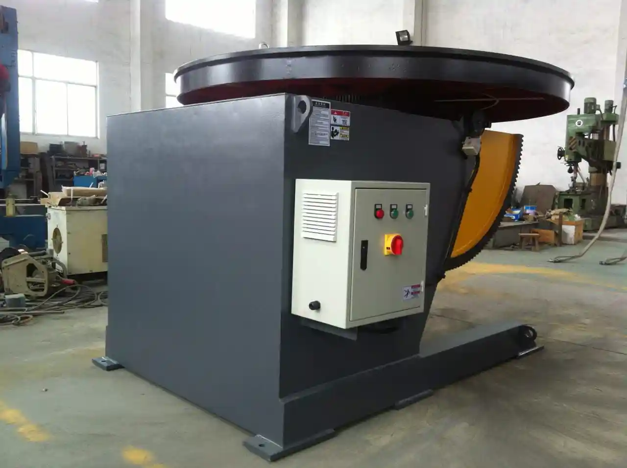
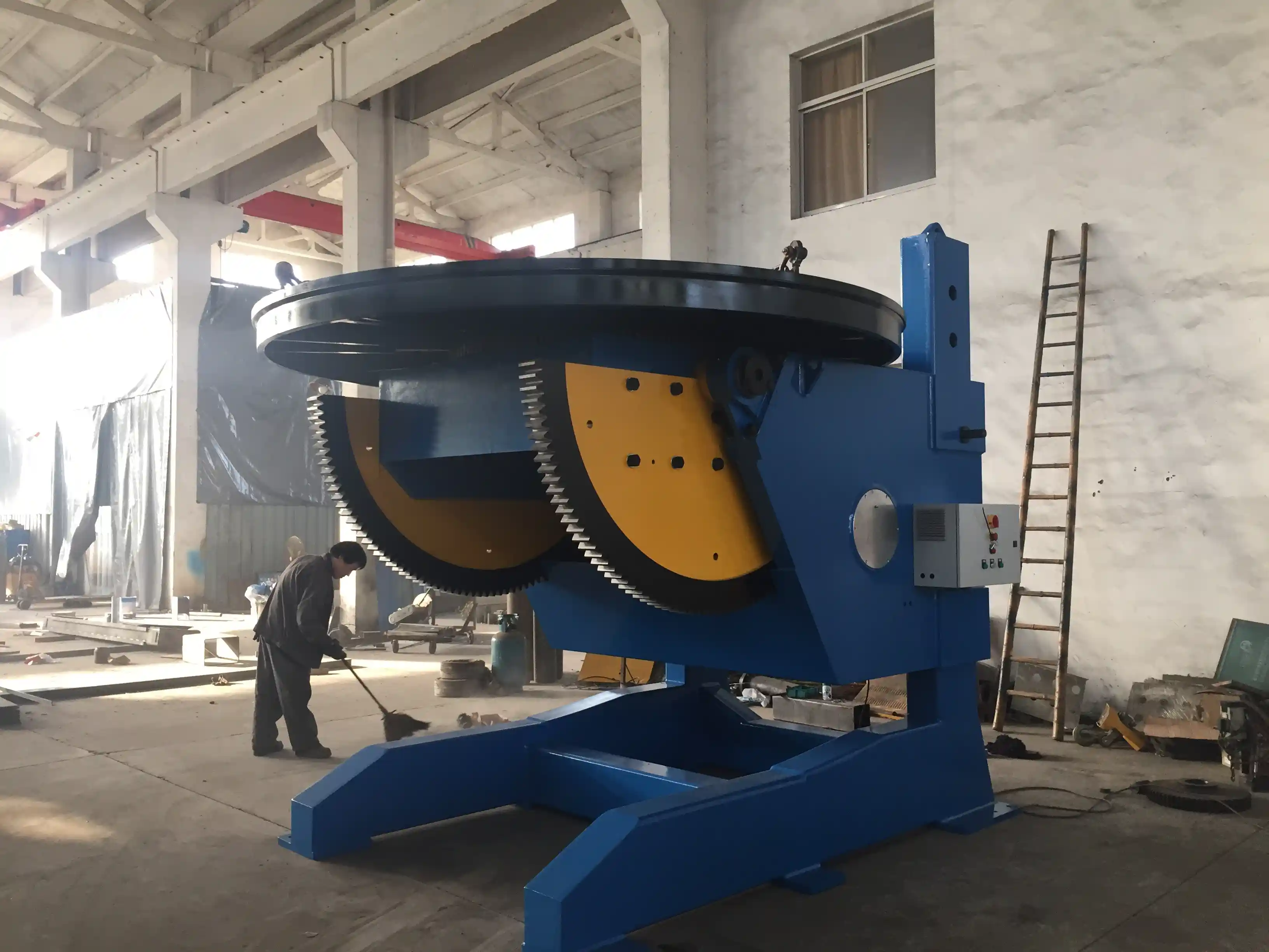
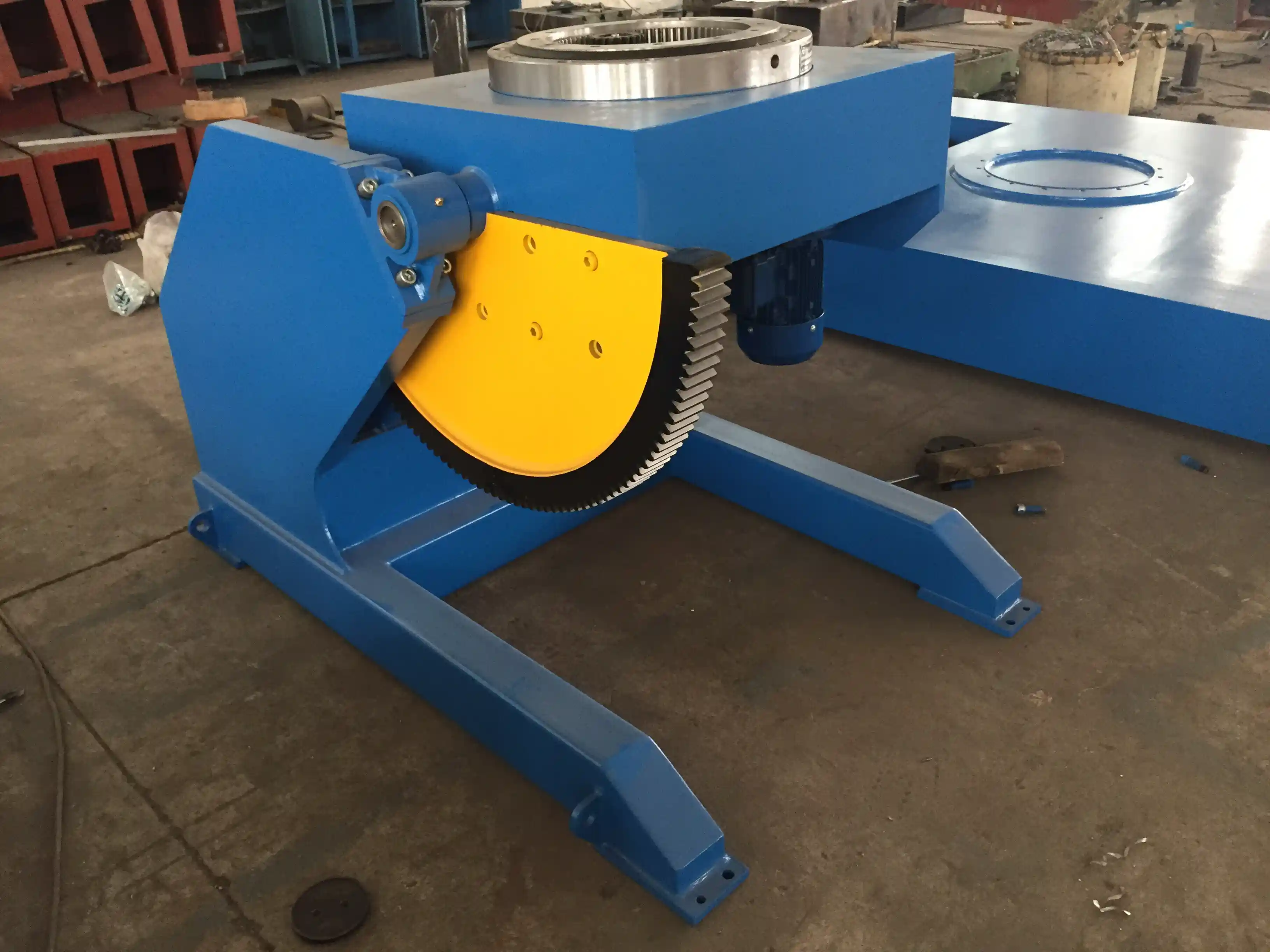
Drive system durability under sustained load also separates volume equipment from job-shop machinery. A 5-ton fixed-height positioner running two shifts a day, six days a week, accumulates roughly 4,000 operating hours per year. Worm gear reducers that perform adequately in intermittent use develop backlash under that duty cycle. Cycloidal reducers last longer because the load distributes across multiple contact points rather than concentrating on a single tooth engagement. When we specify positioners for standard product lines, the reducer type is one of the first questions, not an afterthought.
Drive Systems and Control: Where Real Throughput Gains Come From
Managers often ask me whether a faster motor makes a faster line. Occasionally the answer is yes, but only when the motor is not the constraint. Throughput in standard product manufacturing is primarily a function of three variables that have nothing to do with maximum RPM: speed consistency under load, the range of usable speeds, and the control system’s ability to switch between weld parameters without operator intervention.
AC frequency stepless speed regulation, which is standard on our HGZ series welding rotators and LHBJ positioners, gives the operator precise control from 0.05 to 0.5 RPM on the rotary axis. For circumferential welding of cylindrical products, this range covers everything from root pass deposition rates to final cover pass travel speeds. The key is not that 0.5 RPM is fast. It is that 0.05 RPM is available and stable. A rotator that can hold 0.05 RPM without creeping gives the welder exactly the deposition rate the WPS calls for, which reduces the rework rate on longitudinal and girth seams by a margin that shows up directly in monthly output numbers.
Control integration is the second throughput multiplier. A Siemens PLC with an HMI touchscreen storing 100 preset welding programs means the operator loads the next identical workpiece, selects program 17, and starts welding. No manual parameter entry. No transcription errors. In one boiler panel production line we configured, program presets reduced changeover time between tube panel variants from 12 minutes to under 90 seconds. Across four daily changeovers, that single control feature recovered 42 minutes of arc-on time per shift.
The third factor is the control system’s ability to integrate with upstream and downstream stations. A positioner that operates as a standalone unit creates idle time at both ends. The same positioner with a Profinet or EtherNet/IP interface can receive the next workpiece ID from the loading station’s PLC before the current weld cycle completes. The drive system pre-positions while the operator unloads the finished piece. This overlapping of setup and weld time is where the 15 to 20 percent throughput improvements live, not in marginal motor speed increases.
If your program involves mixed product families with different diameters and weights, the control architecture becomes even more critical. A positioner that can store separate parameter sets for a 2-ton pipe flange and a 5-ton pressure vessel head eliminates the setup recalculation step entirely. The operator selects the part number and the machine configures itself. That is the difference between a machine tool and a production machine.
Tooling and Workholding That Survive Repetition
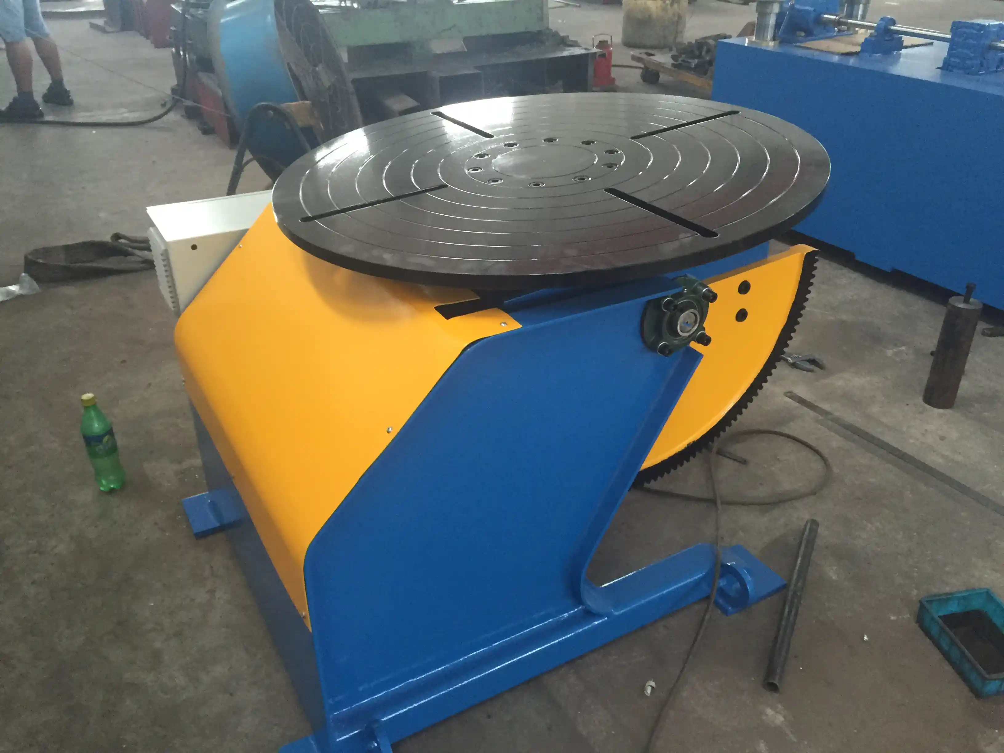
Tooling design for volume production follows one rule: the fixture must locate the workpiece in the same position on the 500th cycle as on the first. This sounds obvious. Most standard positioner worktables come with T-slots and conductive slip rings, which provide the flexibility to mount custom fixtures. The failure point is not the worktable. It is the fixture design itself and the interface between the fixture and the table.
For standard products, we recommend pinned fixturing over clamped fixturing wherever the part geometry allows. A clamp relies on operator judgment for tightening force, and that force varies from person to person and shift to shift. A pinned fixture with hardened locating pins and bushings positions the part within the same 0.1 mm envelope every time regardless of who loads it. On a 1-ton HBJ-10 positioner with a 1,200 mm worktable, the six T-slots provide ample mounting points for a pinned fixture plate that can be swapped in under two minutes when the production batch changes.
Conductive slip rings deserve more attention than they usually receive. In volume production, the positioner rotates continuously throughout the shift. Traditional cable management twists and eventually fails. Slip rings carry welding current and control signals through the rotary joint without cable wrap, which eliminates a recurring downtime cause. On the 5-ton HBJ-50 and 3-ton HBJ-30 fixed-height positioners, the slip ring assembly is integrated into the worktable base, which keeps the current path short and the signal clean. Our field data shows that slip rings reduce rotary joint electrical failures by roughly three to one compared to cable-only setups in multi-shift operation.
Workholding for cylindrical standard products, such as pipe spools or tank shells, shifts the focus to the roller contact surface. Self-aligning welding rotators with ZG45 cast steel rollers hardened to HRC 55 to 60 maintain their profile across thousands of rotation cycles. Urethane rollers wear faster but protect stainless steel surfaces better. The choice depends on the product material. For carbon steel pressure vessels, the steel rollers last longer. For food-grade stainless tanks, the urethane option protects the surface finish from iron contamination and the replacement interval becomes an accepted operating cost.
| Модель | Грузоподъемность | Worktable Diameter | Точность вращения | Drive Type | Best Volume Application |
|---|---|---|---|---|---|
| HBJ-10 | 1 тонна | 1,200 mm | ±0.5° | AC frequency stepless | Small flange and pipe production |
| HBJ-30 | 3 тонны | 1,400 mm | ±0.5° | AC frequency stepless | Medium structural part batches |
| HBJ-50 | 5 тонн | 1,500 mm | ±0.5° | AC frequency stepless | Pressure vessel head and shell work |
| LHBJ-50 | 5 тонн | 900 mm | ±0.5° | Hydraulic lifting | Wind tower section and heavy vessel welding |
| 3-Axis 5T | 5 тонн | Пользовательское | ±0,05 мм | Servo, THK guides | Robotic welding cells, high-precision parts |
Production Layout for Continuous Volume Flow
Equipment selection alone does not deliver volume throughput. The physical arrangement of stations determines whether the line flows or backs up. In standard product manufacturing, we design layouts around the takt time of the slowest station and then work backward to ensure that no upstream station outpaces the constraint.
A common layout for medium-weight cylindrical products, such as pressure vessel shells in the 2 to 6 meter diameter range, places the fit-up rotator station first, followed by the welding rotator, and then the positioner for end-flange welding. The fit-up station uses a hydraulic alignment carriage with laser guidance to achieve the required joint gap and alignment. The 10-ton heavy-duty fit-up rotator we supply for this role provides ±0.5 mm positioning accuracy, which means the circumferential joint arrives at the welding station ready for the root pass without re-alignment.
Between the fit-up and welding stations, we often specify a buffer zone that holds one or two completed fit-ups. This buffer absorbs the inevitable variation when one shell takes longer to align than the next. Without the buffer, the welding station idles while fit-up catches up. With the buffer, the welding rotator maintains its cycle and the daily output count holds steady.
Space constraints in existing buildings often push manufacturers toward compact equipment footprints. A self-aligning welding rotator with integrated drive and idler frames typically occupies less floor area than separate turning rolls on rails. For standard products with consistent diameters, the fixed-center rotator configuration eliminates the need for rail-mounted adjustable frames entirely. The floor space recovered can become the buffer zone or an inspection station. Layout is not just about flow. It is about fitting production volume into the square footage you already have.
Moving from Standalone Machines to Connected Production Lines
The transition from standalone equipment to an integrated line is where standard product manufacturers capture the largest remaining productivity gains. A standalone сварочный манипулятор and a standalone positioner each perform their function well, but the operator walks between them, the crane waits, and the weld cools while the next piece loads. Connected lines eliminate those gaps.
A complete H-beam production line integrates an automatic assembly machine, a gantry welding system, and a straightening machine in sequence. The raw plate enters, the beam exits. For standard product beams in the 400 to 800 mm section range, this configuration delivers consistent output per shift because the stations are balanced to the welding cycle time. The assembly machine feeds the welder at the exact pace the welder can sustain, and the straightening station processes the completed beam while the next one welds.
For tank and vessel production, the integration logic follows the same principle but the equipment differs. A fit-up rotator, a girth welding manipulator on a track, and a positioner for nozzle and flange attachment form a three-station cell. The manipulator’s boom travel range, typically 3,000 to 8,000 mm depending on the model, must match the vessel lengths in the standard product family. We match the LH3040 with its 3,000 mm horizontal travel to smaller vessels and the LH8080 with 8,000 mm travel to long tank shells. The manipulator traverses the length of the vessel while the rotator turns it, laying a continuous circumferential or longitudinal seam without stopping to reposition.
End CTA: The equipment decisions that drive volume output are not always the ones that look impressive on a specification sheet. They are the choices about drive system type, control integration, fixture design, and station layout that compound across thousands of cycles. If you are planning a standard product line or upgrading an existing one, send your part number range and target output volume to jay@weldc.com or call +86-510-83555592. We will match equipment configurations to your actual throughput requirements, not to a generic capacity chart.
What Manufacturers Ask About Volume Production Equipment
Does higher load capacity automatically mean higher throughput?
No. Load capacity determines what you can lift, not how fast you can produce. A 30-ton positioner running one vessel per shift delivers less throughput than a 5-ton positioner running four vessels per shift. The throughput drivers are speed consistency, control integration, and changeover time. Choose capacity for the heaviest standard product in your range with a safety margin, then focus the rest of the specification on the drive and control features that determine cycle time. Overspecifying capacity adds cost without adding output.
Are servo-driven positioners worth the premium for standard products?
In my experience, yes, if the standard product requires tight alignment and the annual cycle count exceeds roughly 1,500 units. Servo drives with encoder feedback maintain positioning accuracy without periodic recalibration, which eliminates a recurring labor cost. For robotic welding cells, the ±0.05 mm repeatability of a 3-axis servo positioner with THK linear guides is effectively mandatory. The robot cannot compensate for a drifting positioner. For manual welding of forgiving geometries, the AC frequency stepless drive on the HBJ series provides sufficient accuracy at lower cost. The decision splits on whether the process can absorb the ±0.5° tolerance of the standard drive or requires the tighter servo tolerance.
What is the most overlooked layout mistake in volume production?
Placing the slowest station in the middle of the line with no buffer capacity on either side. I have walked into plants where a single welding station controls the entire line’s pace, and the upstream fit-up station has nowhere to place completed assemblies when the welder stops. The fit-up operator stops. The downstream inspection station empties. The entire line cycles at the welder’s availability rate, which is always lower than its design rate. Put buffer positions on both sides of your constraint station and the line output stabilizes around the constraint’s average rate rather than its minimum rate.
How do we calculate whether equipment investment will pay back in our volume scenario?
Start with the labor hours the new equipment eliminates per unit, multiply by your annual volume, and multiply by your loaded labor rate. That is the direct saving. Then add the indirect gains: reduced rework from consistent positioning, faster changeover from program presets, and lower inspection rejection rates. Most standard product shops we work with see full payback on positioner and rotator upgrades within 18 to 24 months on labor savings alone. The indirect gains typically shorten that to 12 to 18 months. Share your production volumes and current equipment list with us at jay@weldc.com and we will build the ROI model against your actual numbers rather than industry averages.
Если вам интересно, ознакомьтесь со следующими статьями по этой теме:
Неоценимое значение для практического применения: как позиционеры с фиксированной высотой способствуют развитию морского и судостроительного производства (Часть 2)
Tired of Complex Welding Challenges? How a 3-Axis Positioner Can Boost Productivity by 70%