
In steel structure manufacturing, the gap between cutting capacity and welding throughput is often where projects are lost. A shop may invest in a fast CNC cutting machine but still lose hours moving plates into fit-up, correcting assembly gaps, and waiting for a manipulateur de soudage to return to the starting point. An integrated cutting and welding line is not a single oversized machine. It is a planned sequence of cutting, assembly, welding, straightening, and surface preparation stations sized to produce a consistent section output.
The main difference between an integrated line and a collection of standalone machines is material-flow discipline. When the cut parts, web-to-flange fit-up stations, tack welding positions, main welding manipulators, and straightening units are arranged in one sequence, the shop controls the real bottleneck: the time between value-added operations. That control is more important than any single machine specification.
What an Integrated Cutting and Welding Line Actually Does
An integrated line for steel structure manufacturing takes raw steel plate or profile and moves it through a defined sequence. The typical flow is:
- Plate and profile cutting
- Edge preparation and marking
- Web-to-flange assembly or box column fit-up
- Tack welding and dimensional checking
- Main longitudinal and stiffener welding
- Post-weld straightening
- Blast cleaning and, where required, primer application
For an H-beam workflow, the web and flange plates enter from the cutting area and are transferred to an assembly machine. The machine centers the web, aligns the flanges, and applies enough clamping force to hold the geometry before tack welding. The assembled beam then moves to a gantry or column-and-boom manipulator for fillet welds, or to a multi-torch station for high-volume sections.
For box columns, the sequence is similar, but the fourth side and internal diaphragm fit-up add setup time. This is why a line built only for H-beams often fails when the product mix shifts to columns. The line must be designed around the largest realistic section, not the average section.
From a quality standpoint, the line should be organized so that nonconformities are identified before they reach the welding station. For projects governed by European execution rules, EN 1090-2 [1] sets the technical requirements for execution classes and dimensional tolerances. For American structural steel projects, AWS D1.1/D1.1M [2] remains the primary welding code. A line layout that makes inspection access difficult will eventually create costly repair loops.
Core Equipment Chain: From CNC Cutting to Column-and-Boom Welding
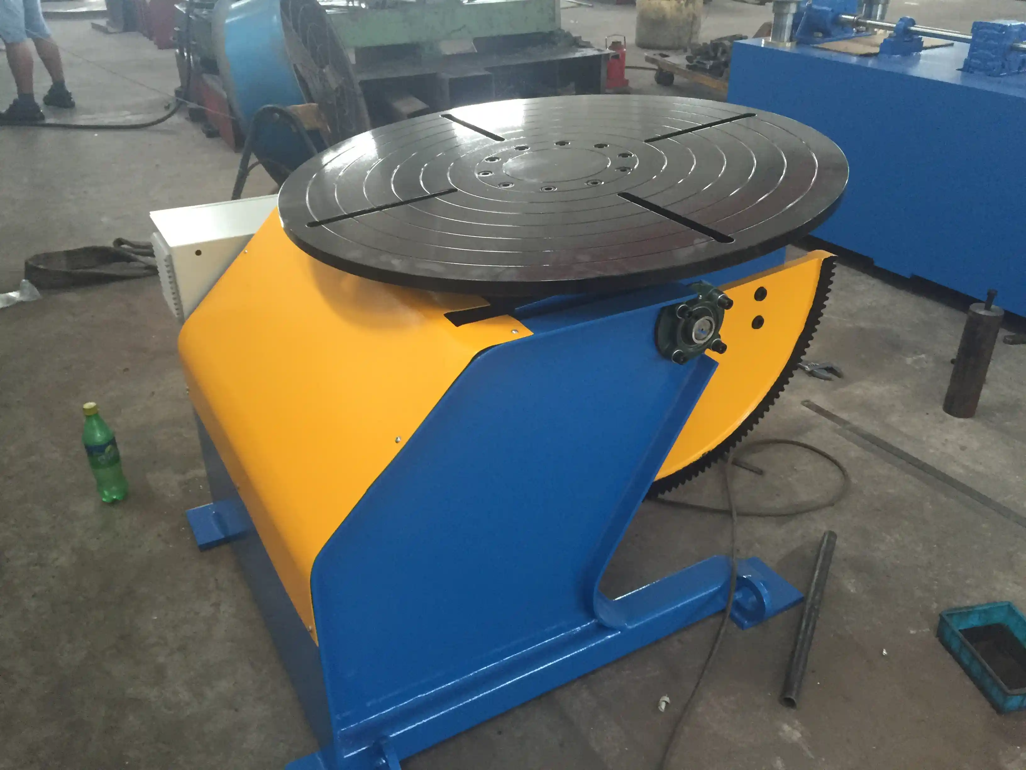
The equipment chain should be selected by material thickness, section depth, and annual tonnage. Not every steel structure shop requires a laser cutting machine, and not every shop should rely on a single flame cutting table.
Cutting Stations
For medium and thick plate, CNC plasma and flame cutting are practical because they balance capital cost, kerf control, and processing speed. A Découpeur plasma CNC handles plate up to medium thickness with good edge quality when the amperage, gas flow, and torch height control are set correctly. For thinner plate and complex profiles, a Machine de découpe laser offers narrower kerf and better dimensional stability, but its operating cost must be compared against the required accuracy.
Flame cutting remains useful for very thick plate because it tolerates surface condition and scale more readily than laser cutting. The edge quality and angularity of thermal cuts are classified under ISO 9013 [3]. When the project specification calls for a specific cut quality class, the cutting station must be checked against that class rather than a general “good cut” standard.
Assembly and Fit-Up
After cutting, the web and flange components move to an automatic Assemblage de la poutre en H machine. The assembly station should provide mechanical centering, clamping, and repeatable web-to-flange alignment. If this station relies too much on manual measurement, the benefits of CNC cutting are lost at the next operation. In a well-integrated line, the assembly machine is not a separate isolated fixture; it is the bridge between cutting accuracy and weld consistency.
Welding Stations
The main welding station is usually a Manipulateur de soudage ou un Machine à souder à portique. The manipulator is selected by horizontal travel, vertical travel, boom reach, and rotation range. For long beams, the gantry system may be a better fit because it moves over the workpiece instead of requiring the workpiece to be repositioned repeatedly.
Column-and-boom systems only pay off when the manipulator travel, foundation, and part positioning are coordinated. <L'espace de l'atelier est trop petit ? Comment les rampes à colonnes permettent de gagner de l'espace au sol 50% tout en renforçant la sécurité et l'efficacité> covers how compact manipulator placement reduces handling without sacrificing reach.
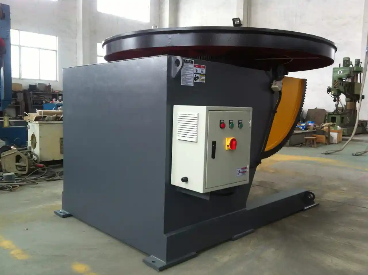
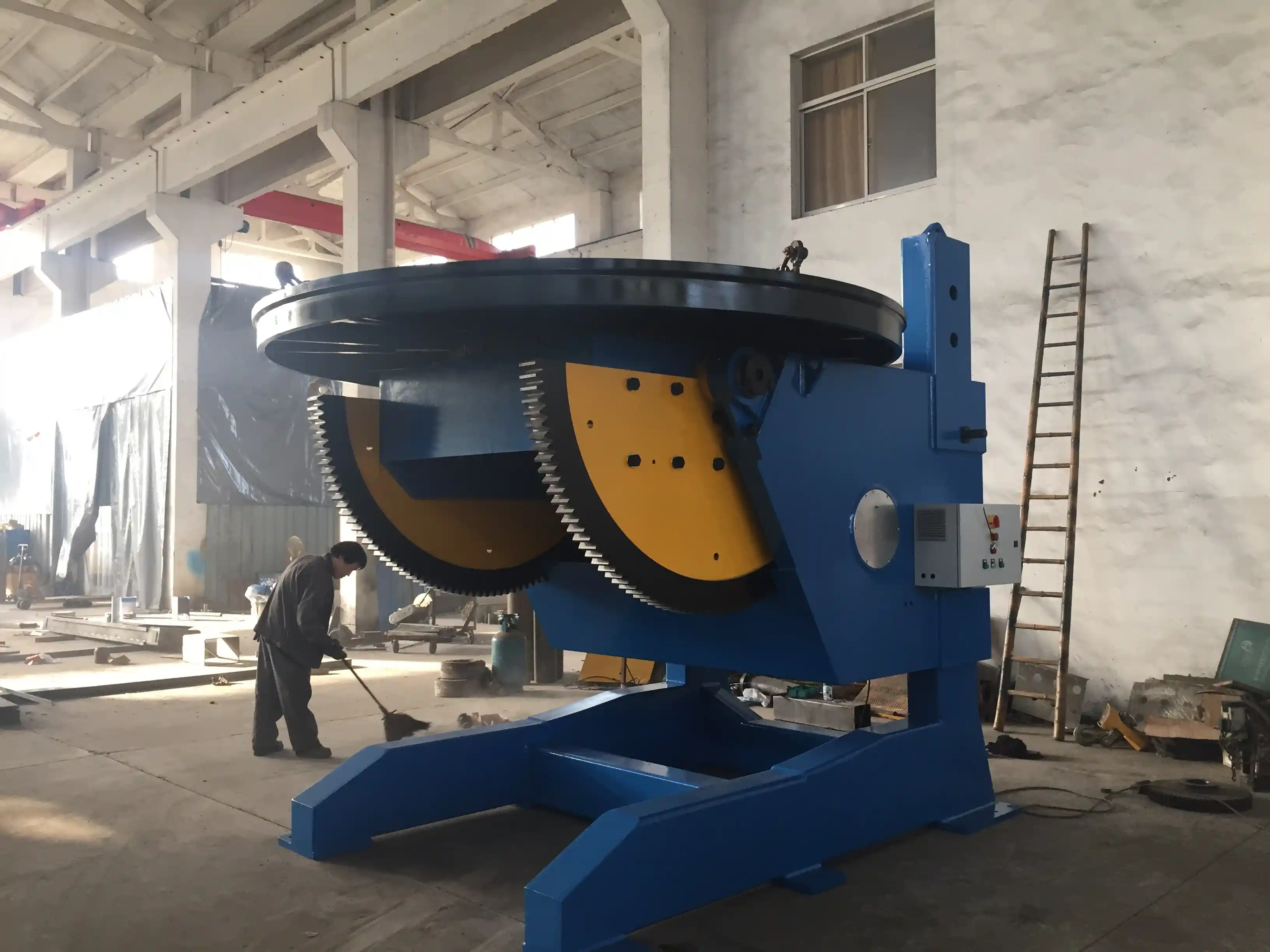
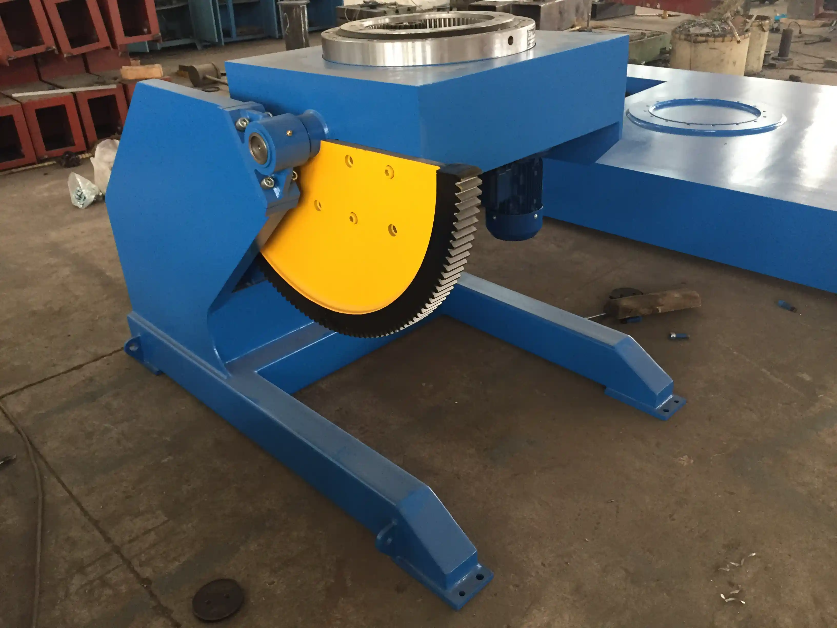
Heavy or asymmetric sections require more than a large welding head. Rotary positioners, turning rolls, and adjustable roller stands are used to rotate the section into the flat or horizontal position. This is especially important for closed sections, conical transitions, and large built-up members that cannot be repositioned by crane during welding.
Long or heavy sections are not stable simply because a fixture can hold them. <Maîtriser la fabrication lourde : Comment les supports à rouleaux grimpants deviennent la pierre angulaire d'un soudage efficace> covers the support and alignment practices that prevent movement during turning and welding.
Post-Weld Correction
After welding, built-up steel sections pull, bow, or twist because of residual stress. A Machine à redresser corrects flange and web distortion while the section is still moving through the line. If straightening is treated as an afterthought, the line will accumulate rework and the final dimensional check will become the bottleneck.
Mid-Project Review: Align the Line Before Adding Capacity
If you are currently comparing a fast cutting table with a slower assembly station, or if the welding manipulator is waiting because fit-up is inconsistent, the issue is usually line balance rather than machine speed. Before buying an additional welding head, define the hourly section flow you want to achieve and then check which station consistently limits that flow. If you need help with a line-level review, send your section size range and annual tonnage to jay@weldc.com and request a cutting-to-welding balance analysis.
Process Data and Quality Control Points
An integrated line only improves quality if the process data is collected at the right points. The most useful checks are not final inspection reports alone; they are in-process measurements taken after each major operation.
| Process Stage | Key Control Point | Typical Tolerance or Standard Reference |
|---|---|---|
| Thermal cutting | Edge squareness and cut roughness | ISO 9013 [3] |
| Assembly | Web centering and flange gap | EN 1090-2 [1] |
| Tack welding | Tack length, spacing, and removal | AWS D1.1 [2] |
| Main welding | Weld size, profile, and sequence | ISO 5817 [4] or AWS D1.1 [2] |
| Straightening | Flange flatness and member bow | EN 1090-2 [1] |
| Final inspection | Weld visual and NDT scope | Project specification and code |
Welds should be evaluated to the quality level defined by the project. In ISO-based projects, ISO 5817 [4] gives three quality levels for fusion-welded joints: B, C, and D. For structural steel, the default acceptance class is typically specified in the execution standard or contract. In American practice, AWS D1.1 [2] defines weld acceptance criteria through visual inspection and, when required, ultrasonic or magnetic particle testing.
A manufacturing control system should also cover procedure qualification, welder performance qualification, and equipment calibration. ISO 3834-2 [5] provides a useful framework for comprehensive quality requirements in fusion welding. The goal is not documentation for its own sake. The goal is to make process variation visible before it becomes a weld defect.
Production Capacity Planning and ROI Factors
Capacity planning for an integrated line should begin with the annual tonnage target and then be converted into a daily section count. The daily section count is more useful than tonnage alone because it accounts for section size and weld length. A line that handles 50 light beams per shift is different from a line that handles 8 heavy built-up columns per shift.
The main capacity drivers are:
- Number of available arc hours per shift
- Deposition rate per welding station
- Fit-up time per section
- Crane handling time between stations
- Straightening and correction time
- Inspection hold time
A common mistake is to compare only cutting speed. If cutting is already faster than assembly and welding can consume, extra cutting capacity will simply create more work-in-progress in front of the fit-up station. The better metric is the time required for one complete section to pass from raw plate to accepted product.
For shops that produce round or tubular members alongside open sections, the handling and rotation strategy must also be considered. The same girth-weld logic used for pipes applies when structural steel includes circular columns or large-diameter bracing members.
Round members inside a steel structure require the same rotation and alignment discipline as pipe fabrication. <Rotateurs de tubes et rouleaux de tournage : Équipement essentiel pour la fabrication moderne de pipelines> covers the equipment and setup details that keep cylindrical sections moving through the weld station.
Common Integration Risks and How to Address Them
The most frequent problems in a steel structure production line are not machine failures. They are integration failures between stations.
Mixed Section Sizes
A line set up for a narrow range of beam depths may lose efficiency when the product mix changes. The assembly station and welding manipulator must be selected for the largest practical section, with handling fixtures that can be changed quickly for smaller sections. This reduces the risk of creating a second manual line inside the same shop.
Material Flatness and Cut Accuracy
Web and flange plate that enters the assembly station with bow or wavy edges will not produce a clean fit-up. Cutting quality, plate storage, and straightening before assembly should be managed as one system. The tolerance for cut edge quality should be referenced to ISO 9013 [3] or the project specification.
Foundation and Rail Alignment
Welding manipulators, gantry systems, and rail-mounted rotators require level foundations and correctly aligned tracks. If the foundation settles or the rail spacing changes, the welding head loses its relationship to the workpiece. This produces inconsistent weld placement even if the machine control system is accurate. The foundation should be inspected before installation and after heavy equipment movement.
Waiting Time at Weld Stations
Waiting time is often caused by poor tack weld quality. Poorly located or undersized tacks allow joint movement during welding, leading to stops for repair. Tack welding should be treated as part of the welding procedure, not as a temporary noncritical step. This is especially important for long beams and closed sections, where accumulated distortion becomes difficult to correct.
Straightening Capacity
If the straightening machine can only handle smaller sections than the welding line, the bottleneck will move to the end of the line. The straightening unit should be selected with enough capacity to correct the flange and web distortion of the largest section the line is intended to produce.
Plan Your Steel Structure Line Around Measured Throughput
If you are preparing a new line or upgrading an existing workshop, the first step is not to select a single machine. The first step is to confirm the section range, annual tonnage, weld length, and required quality class. From there, the cutting, assembly, welding, straightening, and inspection stations can be specified to match one another.
WUXI ABK Machinery supplies the core units used in integrated steel structure lines, including CNC cutting machines, H-beam assembly machines, welding manipulators, gantry welding systems, and heavy-duty positioners. The company can help with line layout and capacity matching rather than quoting separate machines without context. Send your section size range and annual tonnage to jay@weldc.com or call +86-13815101750 for a technical review of your cutting-to-welding flow.
Questions fréquemment posées
What is the difference between a cutting-only line and an integrated cutting and welding line?
A cutting-only line stops at the cut part. An integrated line continues through assembly, tack welding, main welding, straightening, and inspection. The integrated approach is intended to reduce handling, WIP, and the time lost between cutting and final weld completion.
How many operators are needed for a medium-volume steel structure line?
The number depends on the automation level of each station. A semi-automatic line with CNC cutting, automatic assembly, and a welding manipulator may require one operator at the cutting station, one at assembly, one at the welding station, and one for crane handling and inspection. High-volume lines can reduce direct operators but require more skilled process control and maintenance staff.
Can an integrated line handle both H-beams and box columns?
Yes, but the line must be designed for the largest section in both families. Box column production adds internal diaphragm work, side closure, and more handling cycles. If box columns are part of the product mix, the assembly and welding stations should be selected with that cycle time included from the beginning.
What tolerances should be specified during acceptance testing?
Acceptance tolerances should come from the contract or applicable execution standard. For European structures, EN 1090-2 [1] provides the dimensional tolerances. For American structural steel, AWS D1.1 [2] applies to welding. The cutting equipment should also be checked against ISO 9013 [3] for cut edge quality.
How long does installation and commissioning take?
The time depends on the number of stations, foundation condition, automation level, and the complexity of the control system. A medium-size integrated line may take weeks for installation and commissioning. The best approach is to define station-level acceptance tests before the equipment arrives so that commissioning does not turn into an open-ended correction process.
References
[1] EN 1090-2:2018, Execution of steel structures and aluminium structures — Part 2: Technical requirements for steel structures.
[2] AWS D1.1/D1.1M:2020, Structural Welding Code — Steel.
[3] ISO 9013:2017, Thermal cutting — Classification of thermal cuts — Geometrical product specification and quality tolerances.
[4] ISO 5817:2014, Welding — Fusion-welded joints in steel, nickel, titanium and their alloys — Quality levels for imperfections.
[5] ISO 3834-2:2021, Quality requirements for fusion welding of metallic materials — Part 2: Comprehensive quality requirements.
Si cela vous intéresse, consultez ces articles connexes :
Les problèmes de soudage des tours d'éoliennes se répètent : Comment les rotateurs de ligne de culture intelligents augmentent la productivité par 50%
Faible efficacité dans le soudage de groupes de pipelines : Comment les rayonnages à rouleaux intelligents augmentent la productivité par 50%
Le pilier central de la fabrication lourde : Les performances exceptionnelles des supports à rouleaux dans les processus clés
 English
 Español
 Français
 Deutsch
 Português
 Русский