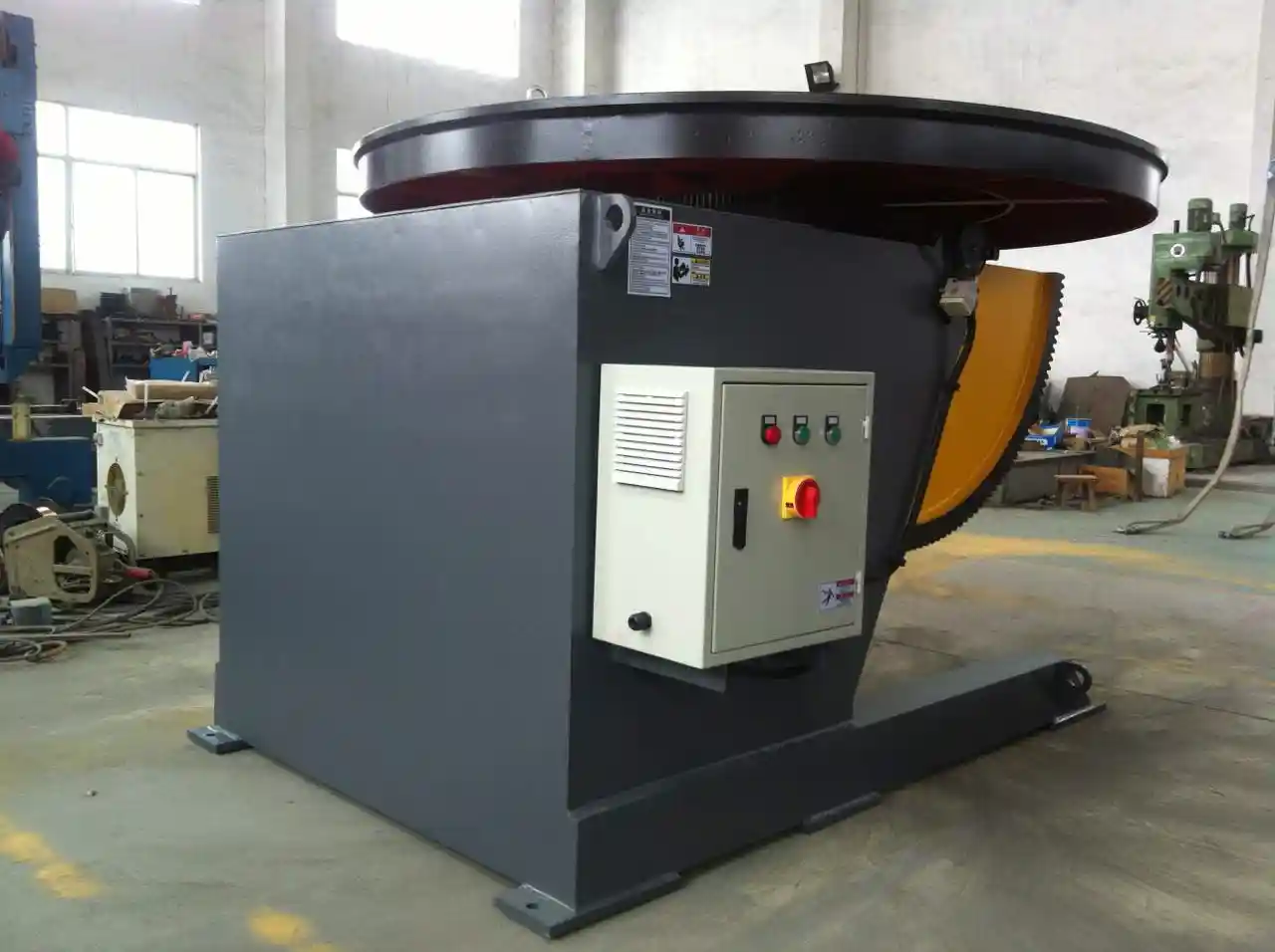
Complex weldments rarely present every joint in the same favorable position. Pressure vessel heads, excavator booms, crane segments, and wind tower flanges can force a welder to work overhead, vertical, or stretched beyond a comfortable arc length. A tilting welding positioner addresses this by moving the workpiece instead of asking the operator to fight the part. The machine supports the component and tilts it into a position where the weld can be performed with better travel angle, work angle, and arc control.
That change seems simple, but it has a large effect in heavy fabrication. When a joint is turned from overhead to flat or from vertical to horizontal, a weld procedure becomes easier to execute consistently. For structural work governed by AWS D1.1, the position and progression need to stay inside the limits of the qualified welding procedure [1]. A positioner helps the fabricator hold that access window repeatably.
What Makes Complex Welds Difficult to Access
Access problems usually show up as one or more of the following: weld face out of reach, insufficient room for the torch head, awkward body position at the joint, or a heavy assembly that is difficult to turn and reset between passes. Cylindrical components often require circumferential welds. Without rotation, the operator must stop, climb, or re-rig the part. With controlled rotation, the joint can move continuously under the torch.
Overhead and vertical positions are not automatically defective, but they are more demanding. Gravity works against the molten pool, and operator fatigue increases. Manual out-of-position welding may still be accepted where procedure-qualified, but access and repeatability usually improve when the work can be positioned for flat or horizontal welding. That is why many fabrication lines use positioners for circumferential seams, girth welds, flange root passes, and multi-face structural parts.
How Tilting Welding Positioners Work
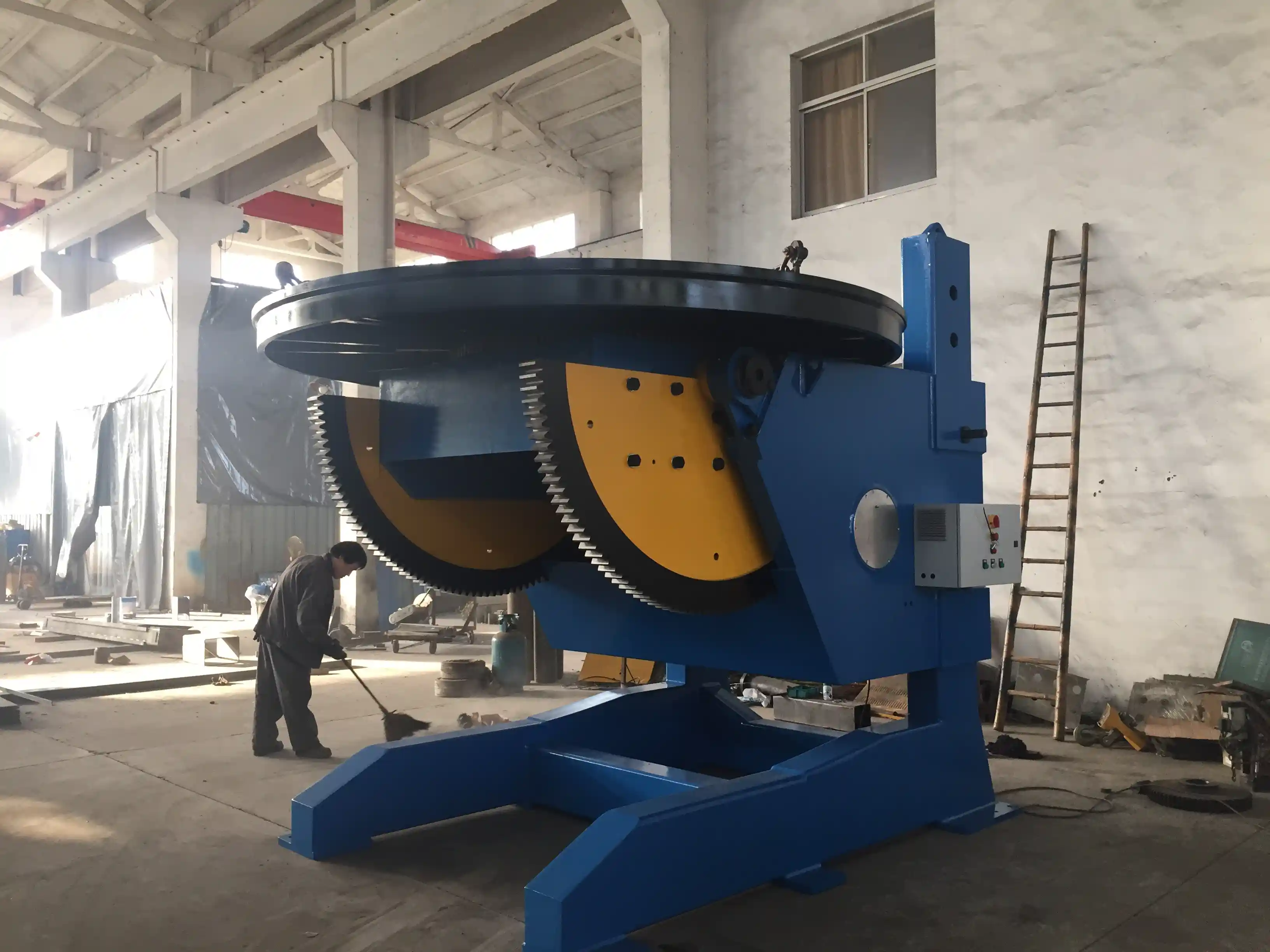
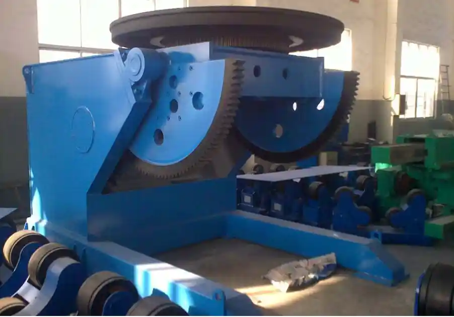
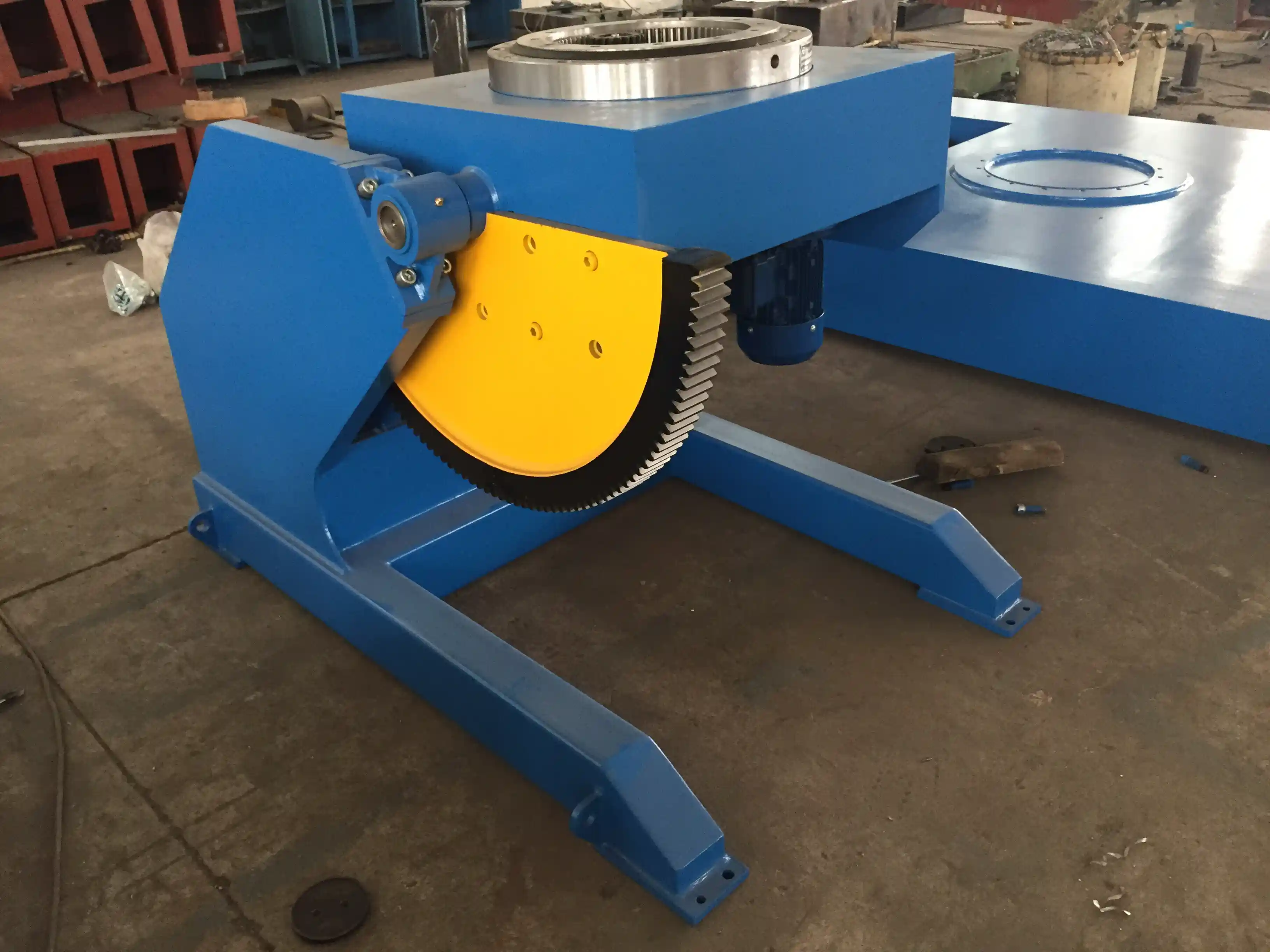
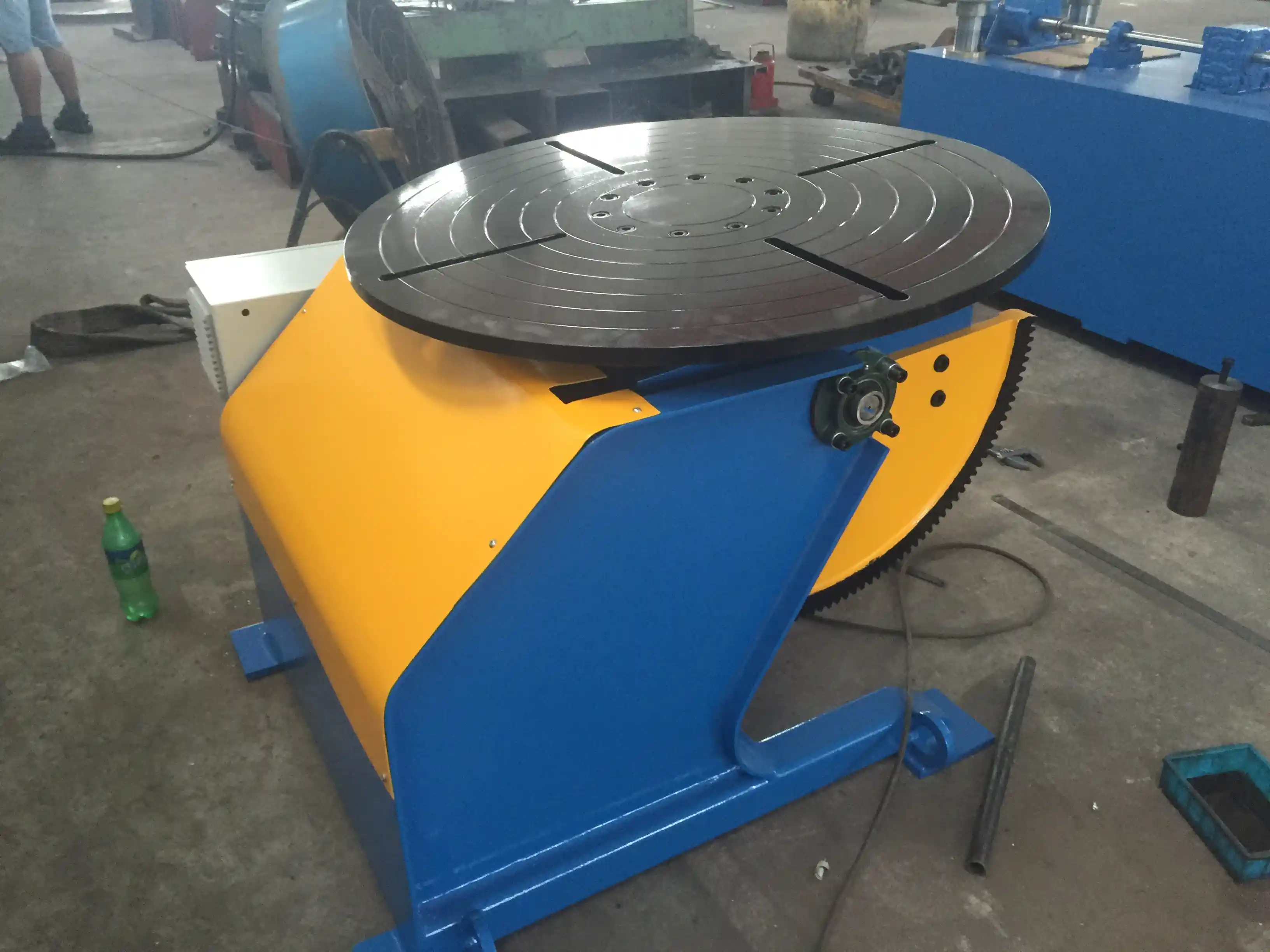
A tilting welding positioner has two or more motion axes. The most common combination is a powered turntable for rotation, a tilt mechanism for angle control, and sometimes a turning or lift axis. The table uses T-slots or fixtures to secure the workpiece. A slewing bearing carries axial, radial, and overturning loads while the drive system delivers low-speed, high-torque rotation. Common rotation ranges are approximately 0.05 to 0.5 RPM on heavy plate-positioning machines, with stepless speed control and continuous 360° rotation. Tilt ranges vary by design: many fixed-height units tilt from 0° to 135°, while some L-type designs offer 0° to 120° turning and 0° to 135° tilt depending on the reducer and frame.
In a multi-axis machine, the axes are usually rotation, tilt, and turning. Turning flips the component between faces; tilt changes the angle of the working face; rotation presents the weld seam continuously. For robotic cells, servo drives and higher-accuracy feedback may be specified. In Wuxi ABK’s product range, 3-axis positioners are available in 1-ton to 5-ton configurations with synchronized turning, rotation, and tilting, while larger adjustable-height positioners are offered for heavy wind tower and pressure vessel work. The right configuration depends on the weldment mass, center of gravity, seam location, and cycle plan.
Key Access and Positioning Capabilities
The following table summarizes access-related specifications common on tilting welding positioners used in heavy fabrication. Use it as a starting checklist rather than a universal requirement.
| Access Parameter | Typical Range or Capability | Why It Matters for Access |
|---|---|---|
| Rotation angle | 360° continuous | Presents circumferential seams without rewinding |
| Tilt range | 0–90°, 0–120°, or 0–135° | Moves overhead or vertical joints into flat or horizontal |
| Rotation speed | 0.05–0.5 RPM stepless | Allows controlled travel speed on large diameters |
| Turning angle | 0–120° or 180° depending on model | Flips multi-face parts between passes |
| Worktable height | 1000–2000 mm on adjustable models | Reduces climbing and improves weld reach |
| Précision du positionnement | ±0.5° common; ±0.05 mm on servo 3-axis models | Controls seam location for automation |
| T-slots and slip rings | Standard on many tables | Supports fixturing and continuous rotation without cable twist |
For more demanding robot integration, a 3-axis positioner adds coordinated turning and tilting under PLC control. One example is the Wuxi ABK 3-Axis Welding Positioner, which provides 0–90° tilt, 360° continuous rotation, and 180° turning with servo control. For site layouts that need weld height adjustment during setup, an Positionneur de soudage réglable or larger Lifting Column Positioner may fit the workpiece better.
Solving Common Access Problems in Heavy Fabrication
The access problem usually defines the positioner configuration:
- Overhead joint on a fixed assembly → tilt the weld face down to flat or horizontal.
- Long circumferential seam → rotate continuously while the welding head or manipulator stays in position.
- Multi-face structural part → use turning to change faces without removing and re-rigging.
- High workpiece center of gravity → specify sufficient load capacity, eccentric distance, and center-of-gravity distance; review base stability.
- Cable twisting during rotation → use a machine with conductive slip rings or specify them as an option.
- Frequent part changeover → select fixtures, quick-change tooling, and a control system with preset programs.
When these requirements are clear, the positioner specification becomes simpler. The key is to know the weldment’s center of gravity and not only its mass. A 3-ton part with a large eccentric offset can overload an improperly selected table even when the nominal load rating appears adequate. That is why load charts and maximum eccentric and center-of-gravity limits should be checked before purchase.
For heavy cylindrical work and multi-pass seam welding, tilt and rotation must work together so the operator can stay in position instead of fighting the part. <Fatigué des défis complexes du soudage ? Comment un positionneur 3 axes peut améliorer la productivité par 70%> covers how coordinated axes improve torch access and throughput.
For pipe girth welds, access and arc-position control are tightly linked to table rotation and tilt control. <Comment améliorer la qualité du soudage de tubes grâce à un positionneur de soudage de haute précision> covers the positioning behavior that supports consistent pipe joints.
For vessel fabrication, the turn, tilt, and rotating axes must work with the weld procedure rather than against it. <Solution révolutionnaire pour le soudage des appareils à pression : Analyse technique des positionneurs de soudage rotatifs à 360 degrés> covers the mechanics of rotation and tilt in pressure vessel work.
Need help matching a tilt range to a specific weldment? Send the workpiece weight, center-of-gravity offset, and required tilt angles to jay@weldc.com. A short configuration review can confirm whether a fixed-height, L-type, adjustable-height, or multi-axis machine gives the access you need before you specify equipment.
Selecting the Right Tilting Positioner for Complex Work
Start with the weldment, not the machine. Measure or estimate three values: maximum loaded weight, center-of-gravity distance from the table face, and the eccentric distance created by the part shape. Then define the motions required: rotation only, rotation plus tilt, or turning plus tilt. Add the diameter and length limits to make sure the table and supporting structure clear the part at the full tilt angle.
For pressure vessel work, the weld procedure matters as much as the machine capacity. ASME Section VIII work requires the fabricator to follow qualified welding procedures and positioning conditions [2]. The positioner should therefore be able to reproduce the weld position called for in the procedure without manual re-rigging. If the same shop also works with structural steel, AWS D1.1 will set separate procedure and welder qualification expectations [1].
A common mistake is to specify only the table capacity and ignore tilt torque. At full tilt, the load moment increases and the tilt drive must hold the part without creep. Worm-gear or cycloidal reducers often provide self-locking or low-backlash behavior, but the exact requirement depends on load and safety margin. The machine supplier should confirm the maximum center-of-gravity distance at the proposed tilt angle.
Integrating Tilting Positioners into Automated Cells
In automated welding, access is not only about the human welder. The torch, camera, seam tracker, or robot arm also needs clearance. A tilting positioner becomes a coordinated external axis in these cells. The control system should allow the robot or programmable logic controller to command table position, speed, and tilt. Higher-accuracy servo models with positioning accuracy around ±0.05 mm and repeatability of 0.02 mm are typically more appropriate for robotic arc welding than coarse inverter-driven tables.
When specifying an automated cell, confirm the following:
- Robot interface: ABB, KUKA, FANUC, or Yaskawa compatibility where required
- Control architecture: PLC plus touchscreen or CNC synchronization
- Safety functions: overload shutdown, emergency braking, anti-fall pins, and guarded travel
- Protection level: IP54 or better for spatter and dust exposure
- Feedback: encoder or resolver feedback for position verification
- Wiring: slip rings to prevent cable entanglement during continuous rotation
Under ISO 3834-2, welding equipment and supporting devices are part of the documented quality system and should be included in maintenance and inspection planning [3]. A positioner that drifts or does not hold tilt angle can create undersized welds, missed seam tracking, or rework, so maintenance must be planned from installation.
Maintenance and Setup for Reliable Access
A tilting positioner holds large energy even at low speed. Daily checks should remove welding spatter, inspect the table and T-slot surfaces, and verify that emergency stops function. On a regular basis, torque mounting bolts, inspect the slewing bearing, check gear backlash, and confirm that lubricant covers the tilt and rotation drives. Annual attention should include bearing and seal inspection, re-lubrication, and position accuracy recalibration.
Setup is equally important. Fixture the part so the weld zone stays within reach, the center of gravity stays inside the allowable zone, and the clamp does not block the tilt path. If the part is long or asymmetric, apply counterweights or use a head-tail positioner rather than overloading a single table.
Configure a Tilting Welding Positioner Around Your Weldment
Wuxi ABK Machinery Co., Ltd works with fabrication teams to match rotation, tilt, turning, and height adjustment to the weldment, weld procedure, and production flow. Before inquiry, prepare these details:
- Workpiece maximum weight and center-of-gravity distance
- Required tilt angle, rotation angle, and turning angle
- Weld process and automation interface
- Table or fixture size needed
- Factory clearance and available height
Send the information to jay@weldc.com or call +86-13815101750. Our engineers can review the application, recommend a fixed-height, L-type, adjustable-height, or 3-axis configuration, and provide the technical data needed for procurement.
Frequently Asked Questions About Tilting Welding Positioners
What is the difference between tilting and rotating on a welding positioner?
Rotation turns the workpiece around the table axis to present a circular seam or reposition the part. Tilting changes the table angle, typically from a horizontal face to a vertical or declined face. In many machines, both functions are driven independently, so the operator can tilt the joint to the preferred weld position and then rotate slowly under the torch.
What tilt angle is needed for pressure vessel welding?
The required tilt angle depends on the joint and procedure. Many pressure vessel shops use 0–90° tilt for shell-to-head joints and 0–135° tilt for parts that need to be repositioned between passes. The positioner should hold the angle stably because vessel work often involves long arc-on cycles and heavy parts.
Can tilting positioners work with robotic welding?
Yes. Select a servo-driven model with adequate positioning accuracy and a robot-compatible control interface. The machine must stop and hold the commanded position without drift, and safety interlocks should be integrated into the cell.
How do I size a tilting positioner for an offset load?
Do not use mass alone. Check the load chart for maximum eccentric distance and maximum center-of-gravity distance at the planned tilt range. If the part is near or beyond those limits, choose a larger table, use counterweights, or evaluate a head-tail configuration.
References
[1] American Welding Society, AWS D1.1/D1.1M, Structural Welding Code—Steel.
[2] American Society of Mechanical Engineers, ASME Boiler and Pressure Vessel Code, Section VIII, Rules for Construction of Pressure Vessels.
[3] International Organization for Standardization, ISO 3834-2, Quality requirements for fusion welding of metallic materials — Part 2: Comprehensive quality requirements.
Si cela vous intéresse, consultez ces articles connexes :
Déport excessif lors du soudage de conduites : solution de positionnement de précision avec plateau tournant de soudage Wuxi ABK
Principaux problèmes et solutions de haute précision des positionneurs de soudage dans les secteurs de l'énergie éolienne et de la construction navale : Analyse technique complète
Améliorer la qualité et l'efficacité dans la fabrication de l'énergie éolienne : Le rôle clé des positionneurs dans le soudage des sections de tours
Solution révolutionnaire pour le soudage des appareils à pression : Analyse technique des positionneurs de soudage rotatifs à 360 degrés
 English
  Español
  Français
  Deutsch
  Português
  Русский