Work-in-progress—the half-finished steel piling up between cutting, fitting, and welding—is one of the heaviest hidden costs in fabrication shops. Most managers fight WIP with scheduling software and inventory tracking, but after twenty years of integrating welding automation lines, I’ve learned that the deepest leverage sits upstream: in how you configure the equipment. Lean equipment configuration reduces work-in-progress by physically eliminating the buffers that batch processing creates. When a CNC cutting machine feeds a welding cell and a positioner sits right alongside, there is simply no floor space for a stack of parts to accumulate. This article explains how to arrange manipulateur de soudages, positioners, turning rolls, and CNC machines into lean cells that sustain continuous flow, even in shops handling diverse mixes.
Why Work-in-Progress Accumulates in Welding Fabrication
Walk through a typical heavy fabrication shop and you will see pallets of cut plate waiting for fit-up, tacked assemblies queued at a welding manipulator, and completed sub-assemblies stacked several deep before the next operation. The root cause is not slow welders. It is the physical separation of process steps into large batches. A CNC plasma or laser machine cuts an entire shift’s worth of parts, then a forklift moves them 50 meters to a remote welding bay. That inventory buffer exists because the cutting and welding stations operate in isolation, each optimized for its own output without regard to overall flow. We have measured this in multiple lines: the longer the distance between stations and the larger the transfer batch, the higher the WIP piles grow.
Setup times reinforce the problem. If a welding positioner takes 45 minutes to change fixtures between product families, the natural response is to run bigger lots. But bigger lots mean longer lead times and more parts sitting idle. In one boiler panel line we worked on, simply moving a small CNC notch-cutting station next to the welding manipulator dropped average WIP by nearly 40 percent because the cutter could supply parts in the rhythm of the welding cycle, not in truckloads.
Lean Equipment Principles for Reducing WIP
Lean equipment configuration borrows directly from the cellular manufacturing logic that transformed automotive machining lines. Three principles apply immediately in welded fabrication.
First, arrange equipment in a flow sequence so that a workpiece moves from cutting to welding to inspection with minimal transport. That often means placing the cutting machine within arm’s reach of the welding cell, ideally in a U-shaped layout that minimizes fork truck traffic.
Second, right-size the equipment to the Takt time. A massive gantry cutting machine that can process 50 tons of plate per shift is impressive, but if the downstream welding station can only absorb 12 tons, the cutter will produce 38 tons of WIP every day. Matching the cutting speed, positioner capacity, and manipulator reach to the actual production pace prevents buildup.
Third, reduce changeover time to the point where economic lot sizes can shrink to one or a few pieces. Quick-change tooling on welding positioners, programmable welding manipulators that store multiple part programs, and CNC machines with automatic nozzle changers all make frequent product switches practical. When a changeover takes minutes instead of an hour, you can run mixed-model sequences that keep the pipeline full without overstuffing it.
Equipment That Enables Lean Welding Cells
Not every machine can support a lean configuration. The equipment must deliver precision positioning, fast setup changes, and the ability to integrate with material handling so that a cell runs with minimal human intervention between parts.
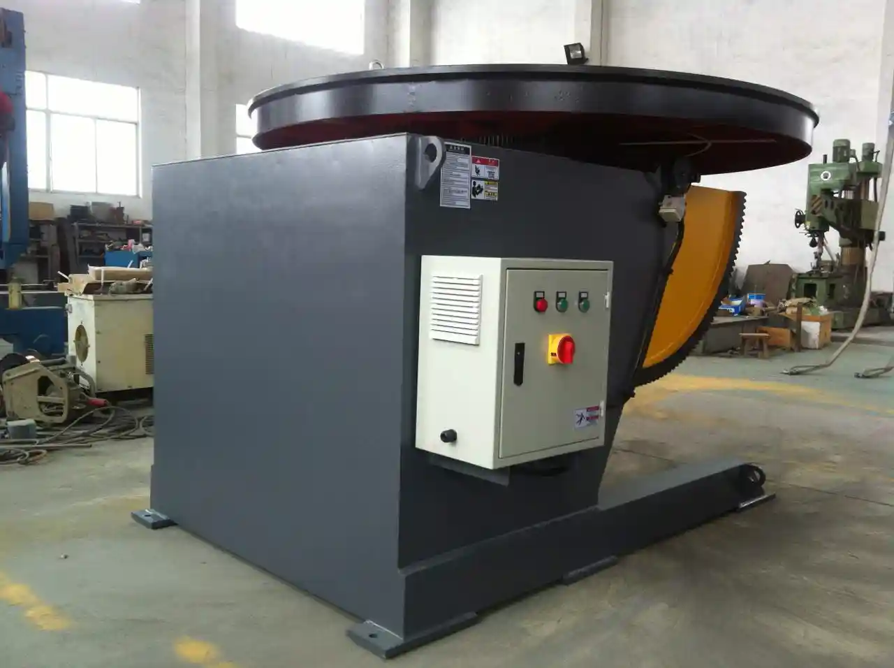
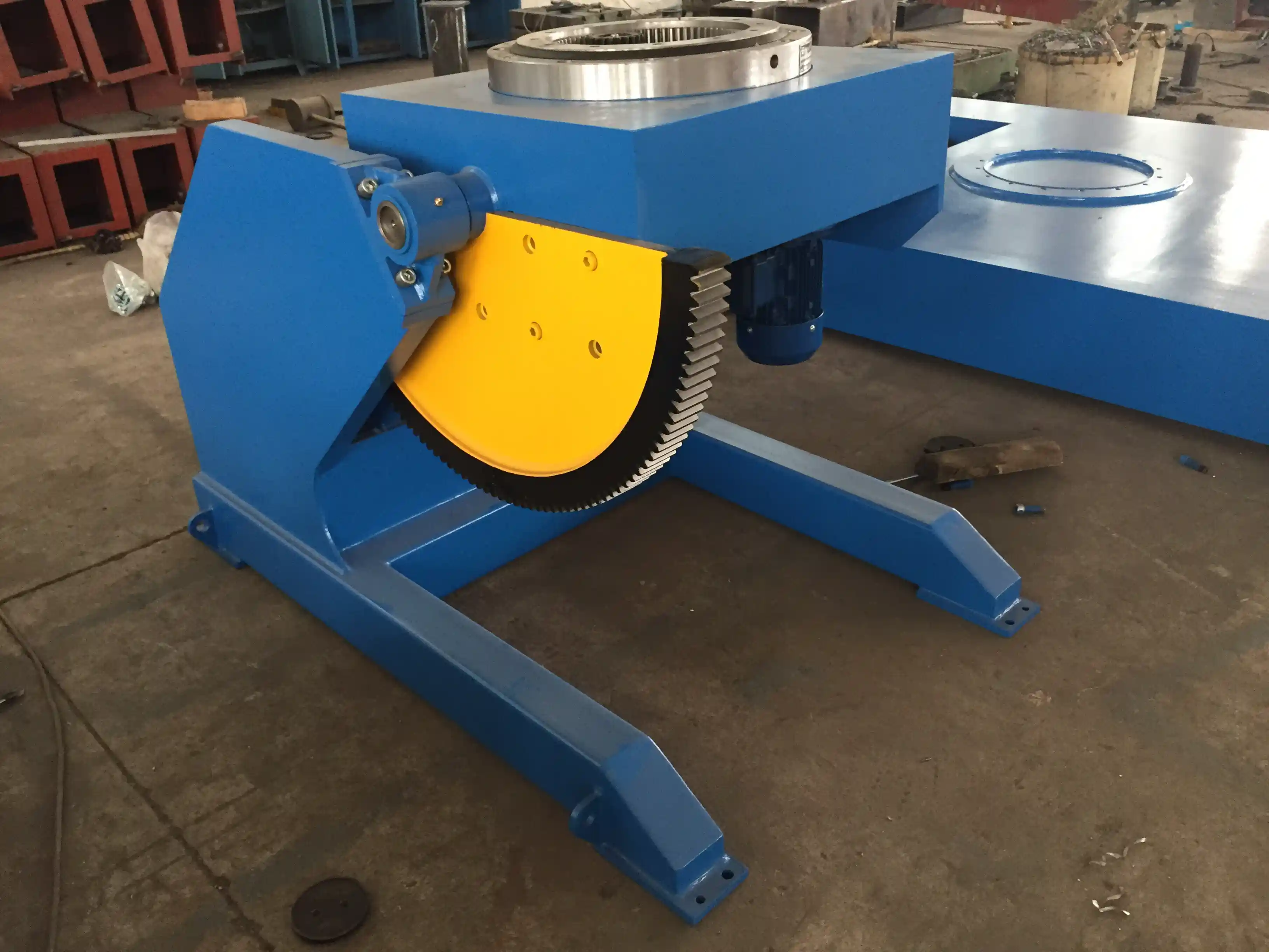
Welding positioners and manipulators form the heart of the cell. For example, a 3-axis welding positioner with a Siemens PLC and pre-stored programs can rotate and tilt a workpiece precisely while the welding manipulator’s boom follows the joint. When we configure an LH-series manipulator with a 1-ton or 3-ton positioner side by side, the operator or robot can move from one part to the next without walking to a distant station. The positioner’s repeatability of ±0.05 mm ensures consistent weld quality without re-teaching, which eliminates rework that otherwise adds WIP.
Table: Positioner Models Supporting Lean Flow
| Model | Load Capacity | Key Feature for Lean Configuration |
|——-|—————|————————————-|
| 1-ton 3-axis positioner | 1,000 kg | Servo drive, ±0.05 mm accuracy, quick program recall |
| 5-ton triple-axis positioning table | 5,000 kg | Dynamic load 5 tons, robot-compatible, rapid fixture change |
| 30-ton adjustable height positioner | 30,000 kg | Hydraulic lift for variable diameters, 100+ preset programs |
Heavy fabrication also depends on welding rotators and turning rolls. A self-aligning, adjustable-height pipe rotator can handle vessels from 500 mm to 4,500 mm diameter without long changeover downtime. Placing the rotator in line with a CNC cutting table that supplies shell plates on a roller conveyor creates a near-continuous flow for pressure vessel and wind tower sections.
If your product mix includes both small valves and large structural frames, choosing positioners with modular tooling plates and quick-clamping chucks becomes essential. Send your typical part range and weights to jay@welc.com, and we can identify which positioner family will let you switch over fast enough to keep the line moving without extra WIP.
Configuring Cutting and Welding for Continuous Flow
The most effective configuration I have seen in operation places the CNC cutting machine directly at the head of the welding cell, forming a compact U-shaped work loop. The operator unloads cut parts onto a short gravity conveyor that slides them to the fit-up station, where a positioner holds the assembly. Once tacked, the part transfers to the welding manipulator without a crane, because the cell has been designed so the manipulator’s boom reach covers the entire cell footprint.
In a structural H-beam line, this approach eliminated two intermediate buffer racks. The CNC plasma cutter produced web and flange plates in kit sequence. A simple fixture on the assembly station aligned them, and a column-and-boom manipulator completed the long fillet welds while a second positioner handled the stiffener welding. Because the line was physically connected, no part waited more than 15 minutes between operations.
Floor space is a legitimate constraint. Not every shop can build a dedicated cell for every product family. In those cases, group equipment around a shared positioner with two or three welding manipulators on floor rails, allowing the cell to reconfigure quickly for different part sizes. Using an adjustable-height welding positioner with a lifting range of 1,000–2,000 mm lets one cell serve both low-profile and tall weldments. The key is to accept a semi-lean state: keep the cutting and welding functions within 10 meters and limit the transfer batch to what one welding shift can consume.
Realizing the Gains: Throughput Improvement and ROI
Warehouse work-in-progress ties up working capital, but factory-floor WIP is even more costly because it masks quality problems and extends lead times. In a fabrication shop that switched from functional layout to a lean cell with an integrated 5-ton positioner and LH-series manipulator, lead time for a family of pressure vessel shells fell from 8 days to 2.5 days. The reduction came not from welding faster, but from eliminating the days parts spent waiting between cutting and welding.
Calculating the return on a lean equipment configuration is straightforward: compare the reduction in WIP inventory value, the labor saved from forklift moves and part searching, and the increase in on-time delivery. Most shops find the payback period for a new positioner and CNC machine arranged in a cell comes inside 12–18 months, often sooner when the freed floor space allows additional workstations.
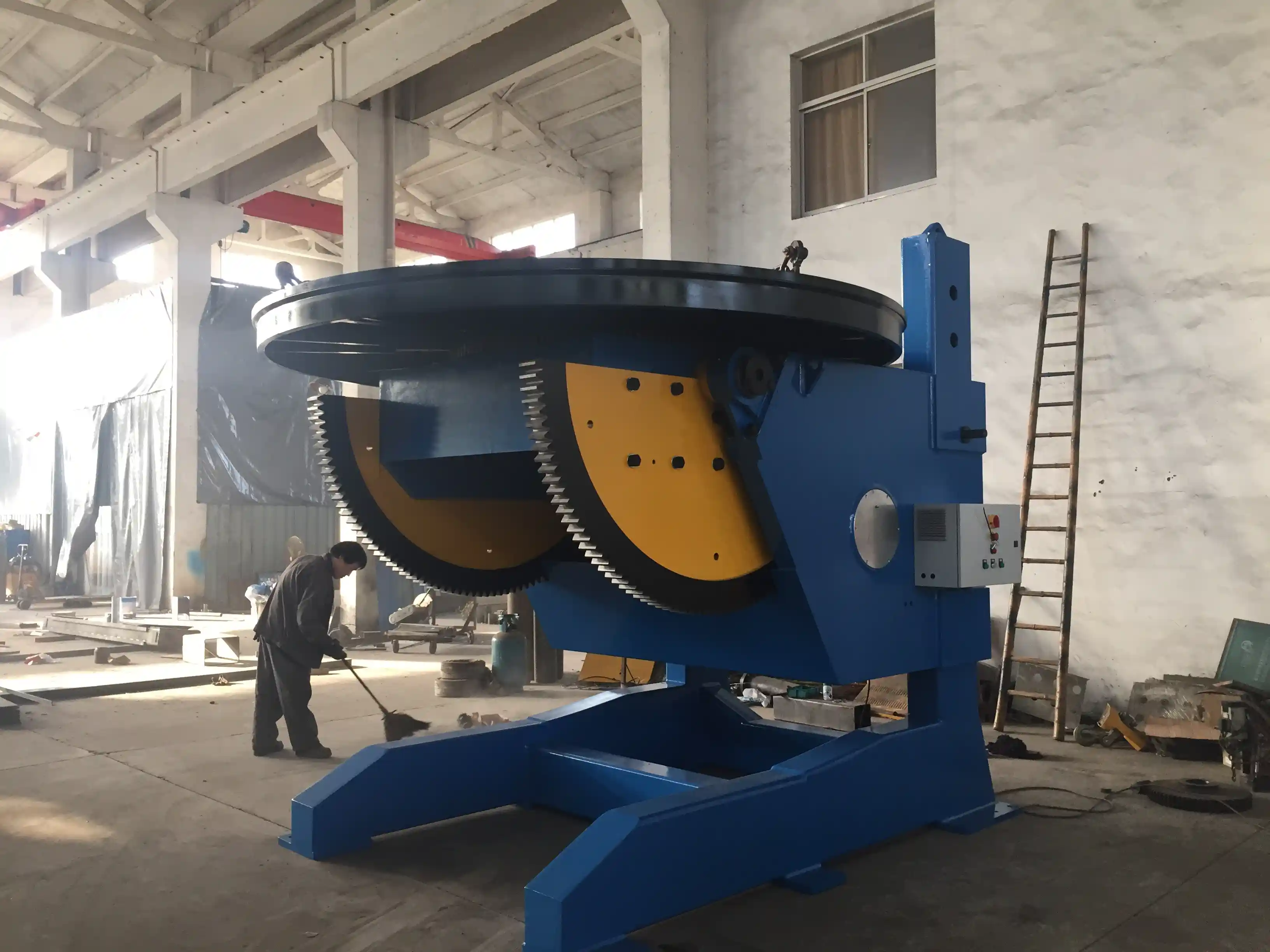
Weighty shops handling 20-ton-plus weldments need robust equipment designed for constant rotation. The ABK L-type and adjustable-height positioner range from 5 tons to 100 tons, with features like hydraulic height adjustment and robot-ready interfaces, support both new lean cells and the gradual conversion of legacy lines. If you are planning a new fabrication line or want to reconfigure an existing one to cut WIP, send your shop layout and product dimensions to jay@welc.com or call +86-510-83555592. We will propose an equipment configuration that fits your space and product mix.
Questions Fabrication Shops Ask About Lean Equipment Configuration
Can a job shop with low volumes benefit from lean equipment configuration?
Yes, often more than a high-volume factory. In job shops, every hour a custom part sits as WIP delays cash collection. Positioning a compact welding turntable and a small CNC cutting machine in a cell shortens the time from raw plate to dispatched weldment. The goal is not to run a continuous line but to eliminate the 2–3 days of waiting that typically occur between operations, even in low-volume work.
Don’t I need to replace all my existing machines?
Not necessarily. Many older manipulators and positioners can be repositioned within a cell layout. The heavier investment is usually in the material handling connections—roller conveyors, lift tables, or a simple overhead jib. If an older CNC machine still holds tolerance, moving it closer to the welding station may be all that is required to cut WIP meaningfully. We often help shops phase the conversion, starting with the most congested product line.
What if my welding mix changes week to week?
Flexible cells are designed for variation. A head-tail welding positioner with programmable rotation, combined with a manipulator that stores multiple welding schedules, can switch between a long shaft and a square frame in less than ten minutes. The configuration is not fixed; it is built around standard interfaces—T-slotted tables, slip rings, modular chucks—so that changeover is designed into the process, not fought against.
How do I calculate whether a lean cell will pay for itself?
Start by measuring two numbers: the current average WIP inventory value for the target product family, and the floor space occupied by buffer racks. A lean cell typically cuts WIP by 30 to 60 percent and reclaims 20 to 30 percent of floor area. Multiply the inventory reduction by your carrying cost, add the rent or opportunity cost of released space, and compare that to the equipment and rearrangement cost. In practice, the reduction in lead time and fewer urgent forklift moves often tip the decision faster than the pure financial calculation.
What if I only have one big CNC cutting machine that feeds several cells?
That is a common constraint. The solution is to batch in the cutting step but break the batch immediately afterward—transfer cut parts in small kits directly to each cell rather than into a central buffer. The cutting machine can run economically while the downstream flow still follows pull logic from the welding cells. If you are uncertain how to split the material flow, send your part mix data and we can model a kit-based feeding system that cuts WIP dramatically without investing in extra cutting capacity.
Si cela vous intéresse, consultez ces articles connexes :
Améliorer la qualité et l'efficacité dans la fabrication de réservoirs et d'appareils à pression : La valeur de l'application principale des positionneurs
Problèmes d'affaissement des revêtements de pipelines maritimes : comment les supports de rouleaux de peinture intelligents font grimper le taux de réussite à 98%
Maîtriser la fabrication lourde : Comment les supports à rouleaux grimpants deviennent la pierre angulaire d'un soudage efficace
Fatigué des défis complexes du soudage ? Comment un positionneur 3 axes peut améliorer la productivité par 70%