
Automatic welding positioners are not simply part-holding accessories. In a robotic welding cell, the positioner becomes an additional controlled axis that must move in coordination with the robot, respond to safety signals, and hold the workpiece accurately enough for the robot to maintain the programmed weld path. A successful integration depends on mechanical stiffness, control architecture, communication setup, safety wiring, and a structured validation process.
One practical way to think about the positioner is as a workpiece-side motion system. ISO 8373 draws a clear distinction between the robot manipulator and auxiliary axes used to reposition the part [5]. Even if the positioner is not called a robot, it has many of the same integration requirements as a servo-driven machine axis.
This guide focuses on what actually has to be checked before automatic welding positioners are connected to robotic systems such as ABB, KUKA, FANUC, or Yaskawa cells. It is written for manufacturing engineers, welding engineers, and factory teams preparing for a robotic cell upgrade or a new installation.
Robot-Ready Positioner Requirements
A welding positioner can be mechanically strong enough for manual welding and still be unsuitable for robotic integration. The robot needs predictable motion, low backlash, stable speed control, and repeatable stopping positions. When a robot welds while the positioner rotates, any variation in the positioner axis appears directly as weld-path error.
Mechanical Interface and Axis Configuration
The first integration question is how many controlled axes the positioner needs. A three-axis positioner usually provides turning, tilting, and continuous rotation. The rotation axis is frequently used as the coordinated external axis during welding, while turning and tilting are used for setup or between-pass repositioning.
For robotic arc welding, the most useful configuration is a positioner that can rotate continuously while the workpiece is held in a stable position. This allows the robot to weld circumferential seams, circular joints, flanges, pipes, and structural parts without repeatedly repositioning the torch. A fixed-position weld, by comparison, forces the robot to work in less favorable torch angles.
The mechanical table must also support the tooling accurately. T-slots, center bores, and fixture dowels should be used to establish a repeatable workpiece location. If the fixture location is not repeatable, the robot will need to re-touch or re-teach points after every part change.
A typical servo-driven three-axis positioner may offer positioning accuracy around ±0.05 mm and repeatability around 0.02 mm when equipped with precision reducers and linear guides. These values are product-specific, so they should be verified against the application tolerance, not assumed to be sufficient for every weld.
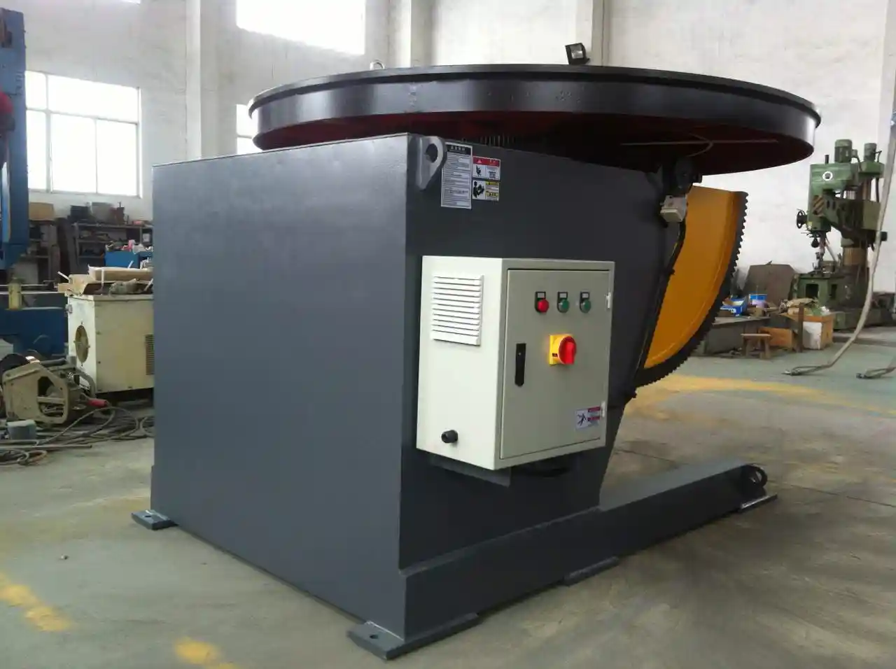
Torque, Stiffness, and Cable Management
Torque capacity is not the same as load capacity. The positioner must be selected for the maximum overturning moment created by the part, fixture, and dynamic acceleration. A heavy part mounted far from the table center can generate a far higher load than the nominal kilogram rating suggests.
Stiffness matters as much as repeatability. If the table deflects during acceleration, the part moves relative to the robot. In heavy fabrication, thin risers, weak fixture plates, and long workpiece extensions are common causes of robot welding defects that appear only during coordinated motion.
Cable management should also be resolved before integration. Turn, tilt, and rotation axes must not twist power, feedback, or safety cables. Conductive slip rings are useful for continuous rotation because they prevent cable entanglement while maintaining power and signal transmission.
Robotic welding only pays off when the positioner holds the part accurately during coordinated motion. <Fatigué des défis complexes du soudage ? Comment un positionneur 3 axes peut améliorer la productivité par 70%> covers how a three-axis positioner reduces repositioning and increases arc-on time.
Control Architecture and Communication
The positioner can be integrated in several ways: as a robot external axis, as an independent servo axis commanded by the robot controller, or as a simple indexing device controlled by digital I/O. The correct choice depends on whether the weld path must be coordinated with the positioner motion.
External Axis Control Options
When the positioner rotation must be synchronized with the robot, the positioner servo drive should be connected to a motion bus that the robot controller can command. Common options include EtherCAT, EtherNet/IP, PROFINET, or the robot manufacturer’s preferred motion interface. In this arrangement, the robot controller can command positioner speed, position, and acceleration in the same motion program.
A simpler approach uses the positioner as an indexing axis. The robot sends a start signal, the positioner indexes to a position, and the robot receives a stop confirmation before welding begins. This is easier to implement but less productive for continuous circular welds because the robot must wait for the positioner to finish each index.
For manual or semi-automatic cells, pulse and direction, analog speed reference, or digital inputs may be sufficient. These methods are not normally recommended for coordinated robotic welding because they do not provide the same closed-loop position control and motion synchronization.
| Interface option | Typical use | Integration note |
|---|---|---|
| Robot external axis over fieldbus | Coordinated rotation during welding | Best for circumferential and complex seams |
| Positioner PLC indexing | Part repositioning between welds | Simple but increases non-arc time |
| Analog speed reference | Manual or semi-automatic processes | Limited position control |
| Digital I/O start/stop | Basic turntable function | Not suitable for coordinated motion |
| Safety fieldbus signals | Safe stop and zone control | Must match robot safety architecture |
Safety Signals and Zone Management
The safety interface is separate from the motion interface. At a minimum, the positioner must provide dual-channel emergency stop signals, drive enable feedback, and safe state confirmation. The robot controller should be able to stop the positioner through the same safety logic that stops the robot.
If the positioner is inside a robot cell, it should not be allowed to move when a safety gate is open. If it is integrated as a collaborative application, power and force limiting may be required. ISO/TS 15066 provides guidance for collaborative robot applications and transient contact limits [3]. Most heavy welding positioners are not collaborative by nature, so they are typically installed behind physical guarding.
The practical rule is that the positioner and robot must share a common safety zone logic. A positioner that continues rotating after an emergency stop or gate interruption creates a serious hazard. The safety functions should be validated during commissioning, not after production starts.
Accuracy, Payload, and Repeatability Checks
Robotic welding tolerates less positioner error than manual welding. A manual welder can adjust the torch in real time; a robot follows the taught path. If the positioner does not return the part to the same location, the robot cannot correct the seam location on its own unless a seam-tracking system is installed.
Load Cases to Verify
Before teaching a robot program, the positioner should be tested with the actual production fixture and a representative part. The test should cover the maximum tilt angle, the longest part, the highest acceleration, and the most off-center load condition.
A load test should include the following checks:
- No visible table deflection or fixture movement
- Rotation speed remains stable at the welding speed
- Stop position repeatability is within the required tolerance
- No unusual vibration or motor current spikes
- No mechanical drift after multiple continuous rotations
- Brake engagement and release are confirmed by the controller
The product’s dynamic load rating should be compared with the real overturning moment. For example, a positioner with a 1-ton nominal load may not handle a 1-ton part mounted on a tall riser at full tilt. The effective load must be calculated from part weight, center-of-gravity distance, and fixture weight.
Accuracy Tests That Matter
ISO 9283 defines performance criteria for manipulating industrial robots, including pose accuracy, pose repeatability, path accuracy, and path repeatability [2]. Although positioners are not always tested as robots, the same concepts are useful. For robotic welding, the most important value is repeatability: can the positioner return the same point after multiple rotations?
A practical verification procedure can include:
| Test | Method | Pass condition |
|---|---|---|
| Reference return | Command a known position after multiple rotations | Position error within process tolerance |
| Repeatability run | Repeat a rotation sequence 10–20 times | Stable weld start point |
| Speed stability | Monitor actual speed during welding pass | No visible speed hunting |
| Stop accuracy | Stop at taught position from both directions | Consistent seam alignment |
| Loaded test | Repeat test with production part | No tool offset change |
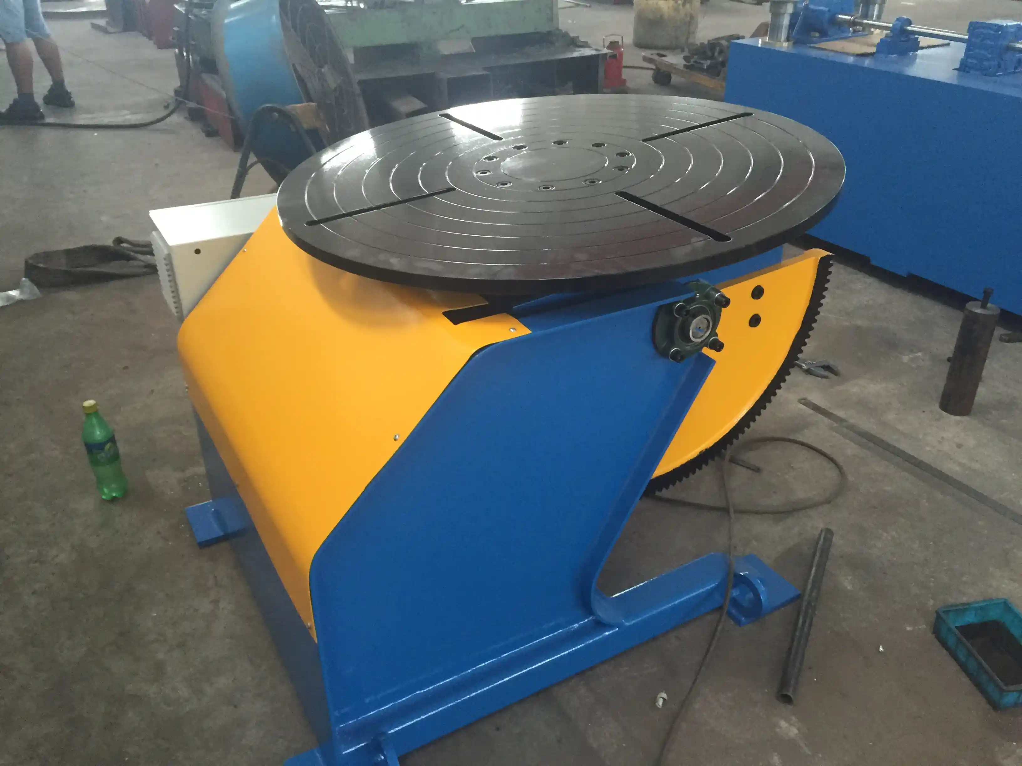
Accuracy problems usually show up first on circumferential welds. <Comment améliorer la qualité du soudage de tubes grâce à un positionneur de soudage de haute précision> covers the relationship between positioner precision and repeatable weld quality.
Safe Integration Workflow
A structured commissioning sequence reduces the chance that a positioner is connected to a robot before the safety functions and basic motion behavior are proven.
Risk Assessment and Stop Function
ISO 10218-2 requires a risk assessment for the complete robot system, including the positioner and any auxiliary equipment used in the cell [1]. ISO 12100 provides the general machinery risk assessment and risk reduction process [4]. The risk assessment should include loading and unloading, teaching, maintenance, unexpected start, loss of speed control, and failure of the positioner brake.
The safety circuit should be tested in all operating modes. At a minimum, verify that:
- E-stop stops robot and positioner motion
- Protective stop stops motion without removing servo power when appropriate
- Gate opening in automatic mode initiates a safe stop
- Teaching mode allows positioner motion only under enabled-device control
- Positioner brake engages when drive enable is removed
- Restart after safety stop requires a deliberate reset action
These tests should be saved as part of the commissioning record. They also provide a baseline for future maintenance and safety audits.
Validation and Teaching
After the safety checks pass, the integration can move to low-speed coordinated motion. Start with the positioner empty, then with the fixture only, then with a representative part. Teach the robot reference points with the positioner in a known home position.
When a coordinated motion program is taught, the robot and positioner should move together at the intended welding speed. If the positioner speed causes the robot to exceed its path accuracy, reduce the speed until the weld path remains stable. The robot’s motion planner may need to be configured to treat the positioner axis as an external axis with known gear ratio and direction.
A useful field check is to run a dry cycle with the welding arc off and observe the TCP behavior. Compare the programmed path with the actual path. If the torch tip oscillates or lags, troubleshoot the positioner drive tuning, communication cycle time, or mechanical backlash before welding.
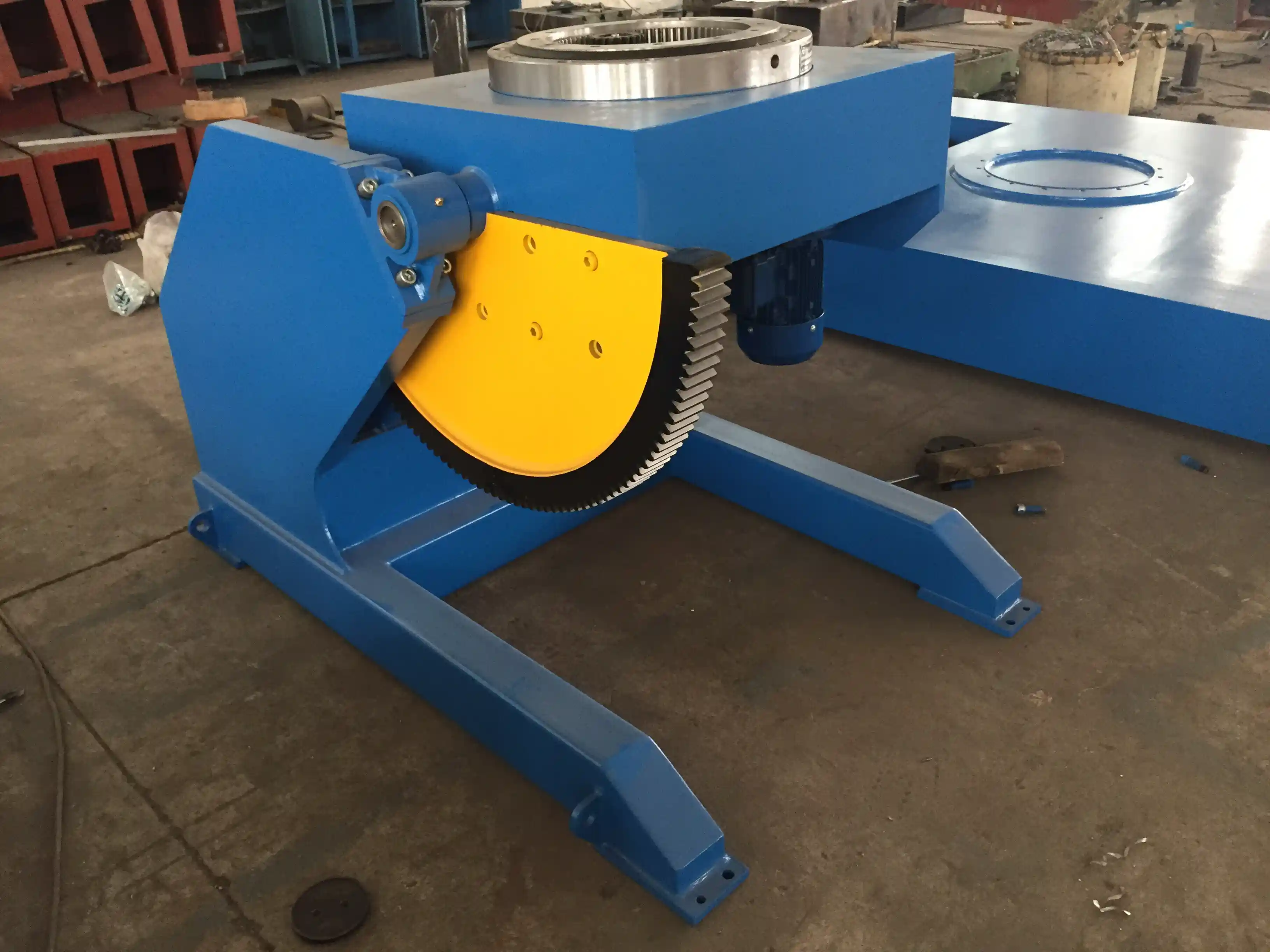
Common Integration Problems and Field Fixes
Most integration problems are not caused by a single major failure. They come from small mismatches in axis direction, communication scaling, brake timing, or mechanical wear.
Positioner-Robot Direction Mismatch
A positioner that rotates in the opposite direction from the robot’s programmed external axis will create an unstable coordinated path. This often happens after a drive replacement or when a positioner is first integrated. The correction is to verify the encoder sign, gear ratio, and motion direction in the robot configuration.
Communication Scaling Errors
If the positioner uses a fieldbus, the position scale must match the drive’s mechanical parameters. A mismatch can cause the positioner to rotate faster or slower than commanded. The result may appear as an inconsistent weld speed or a seam that drifts.
Payload and Center-of-Gravity Errors
Incorrect payload entry in the robot controller can produce unnecessary protective stops or poor path performance. For the positioner, an incorrect center-of-gravity calculation can overload the tilt drive during acceleration. The positioner should be sized using the worst-case part envelope, not the average part.
Brake Timing and Drive Enable
Some systems release the brake before the drive builds enough torque, allowing the table to sag before motion starts. Others engage the brake before the axis is fully stopped, causing a jerk at the weld end. These issues should be tuned in the drive parameters and verified with a loaded test.
Weld Placement after Manual Adjustment
If an operator manually jogs the positioner to improve access, the robot program’s reference frame may no longer match the part. This is especially common when the positioner does not have absolute position recovery. A homing procedure and a clear rule for reference recovery should be defined before operators are allowed to jog the positioner.
Mechanical Wear and Backlash
Backlash in a tilt or rotation axis can create a dead zone. The robot may command a small correction, but the table does not move until the backlash is taken up. This is most visible as inconsistent start positions or small weld offsets. Regular inspection of reducers, gears, and fixture locating surfaces is necessary.
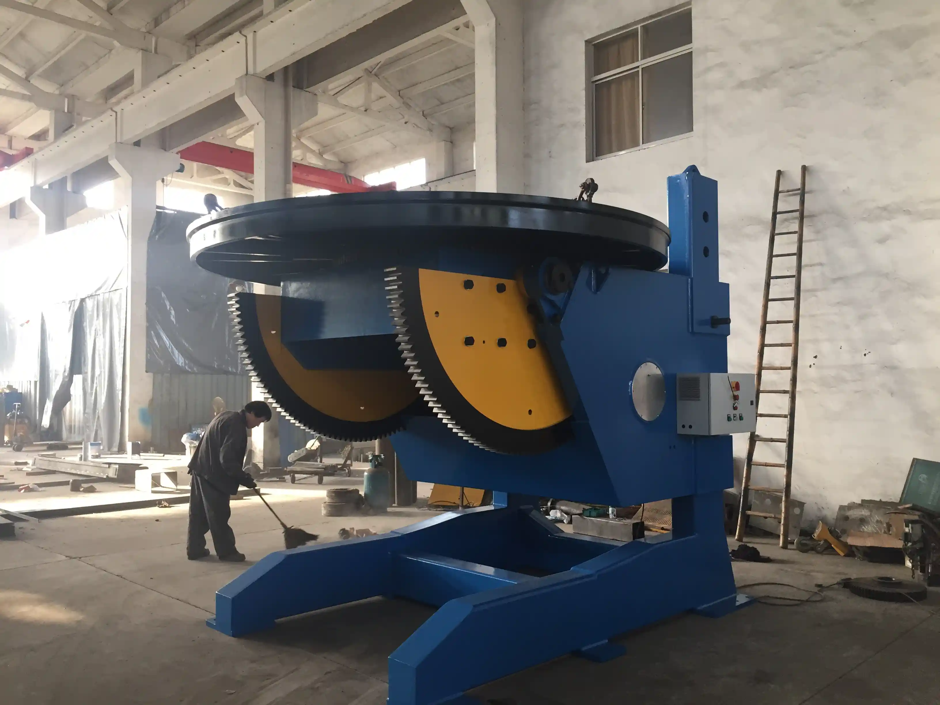
In heavy fabrication cells, positioner stiffness and operator access determine whether a robotic cell reaches stable production. <Une révolution dans le domaine du soudage naval : comment les positionneurs de soudage améliorent la qualité et l'efficacité> covers positioner-driven quality and efficiency gains in ship welding.
Request an Integration Review
Robotic positioner integration is easier to correct during design than after installation. If you are preparing a robotic welding cell, review the positioner selection, axis configuration, safety interface, and communication plan before the equipment arrives on site.
Send the application team at WUXI ABK the following information for a practical integration review:
- Robot brand and controller model
- Positioner rated load and workpiece weight
- Maximum part diameter, length, and center-of-gravity distance
- Required coordinated motion or indexing mode
- Preferred fieldbus or hardwired interface
- Existing safety architecture and cell guarding
Contact WUXI ABK MACHINERY CO., LTD at jay@weldc.com or call +86-510-83555592 / +86-13815101750 with your cell concept. The team can help you confirm whether the positioner should be configured as an external axis, which safety signals must be wired, and what load data the robot program needs before welding starts.
FAQ
Can I use a standard welding positioner with any robot brand?
In many cases, yes. A servo-driven positioner with a standard fieldbus interface can be configured as an external axis for ABB, KUKA, FANUC, Yaskawa, and other robot controllers. The main conditions are that the positioner drive supports the required communication protocol, the safety signals match the robot safety architecture, and the gear ratio and direction are correctly entered in the robot controller.
What is the difference between a positioner axis and a robot external axis?
A positioner axis is a machine axis that moves the workpiece. A robot external axis is a positioner or track that is commanded by the robot controller as part of the coordinated motion system. Not all positioners need to be external axes. If the positioner only indexes between joints, it can operate like a separate PLC-controlled axis. If it must rotate during welding, it usually should be integrated as an external axis.
How accurate does a positioner need to be for robotic welding?
There is no single value because the requirement depends on joint tolerance, weld size, and whether seam tracking is used. A common starting point for precision robotic work is a repeatability better than ±0.1 mm at the part location. However, the actual value must be verified with the production fixture and workpiece, not only from the positioner specification.
What safety signals must be connected for integration?
At a minimum, connect the emergency stop circuit, drive enable feedback, safe stop confirmation, and the protective stop interlock with the cell guarding. The exact signals depend on whether the positioner is wired into a safety PLC, a robot safety controller, or a standalone safety relay. ISO 10218-2 requires the risk assessment to cover the complete robot system, including the positioner [1].
How do I avoid program offset errors after a crash or maintenance?
Define a recovery procedure that includes re-homing the positioner, checking the fixture position, and running a reference-point check before welding resumes. If the positioner has absolute position recovery, verify that the absolute reference is still valid. If not, teach the robot a reference point on the fixture or part and confirm that the weld start position matches the original program.
References
[1] ISO 10218-2:2011, Robots and robotic devices — Safety requirements for industrial robots — Part 2: Robot systems and integration. International Organization for Standardization.
[2] ISO 9283:1998, Manipulating industrial robots — Performance criteria and related test methods. International Organization for Standardization.
[3] ISO/TS 15066:2016, Robots and robotic devices — Collaborative robots. International Organization for Standardization.
[4] ISO 12100:2010, Safety of machinery — General principles for design — Risk assessment and risk reduction. International Organization for Standardization.
[5] ISO 8373:2021, Robotics — Vocabulary. International Organization for Standardization.
Si cela vous intéresse, consultez ces articles connexes :
Problèmes de désalignement lors du soudage de tuyaux : comment les rotateurs intelligents de tuyaux améliorent le taux de réussite des soudures sur les oléoducs
Des soudures parfaites sur des tubes de grand diamètre grâce à un équipement de laminage professionnel
 English
  Español
  Français
  Deutsch
  Português
  Русский