
Specifying a CNC cutting machine is not about picking a catalog number. The real productivity of the system depends on three customization points that most generic articles gloss over: the working table dimensions, the torch arrangement, and the software that ties everything together. I’ve spent over twenty years configuring CNC cutting systems for steel fabricators, pressure vessel shops, and wind tower production lines, and I can say that every successful installation traces back to a few concrete decisions made before the machine is built. This article walks through those decisions from a manufacturer’s perspective, covering the sizing rules, torch combinations, and control system options that procurement engineers and shop floor managers need to lock down early.
Matching Table Size to Workpiece Dimensions and Throughput
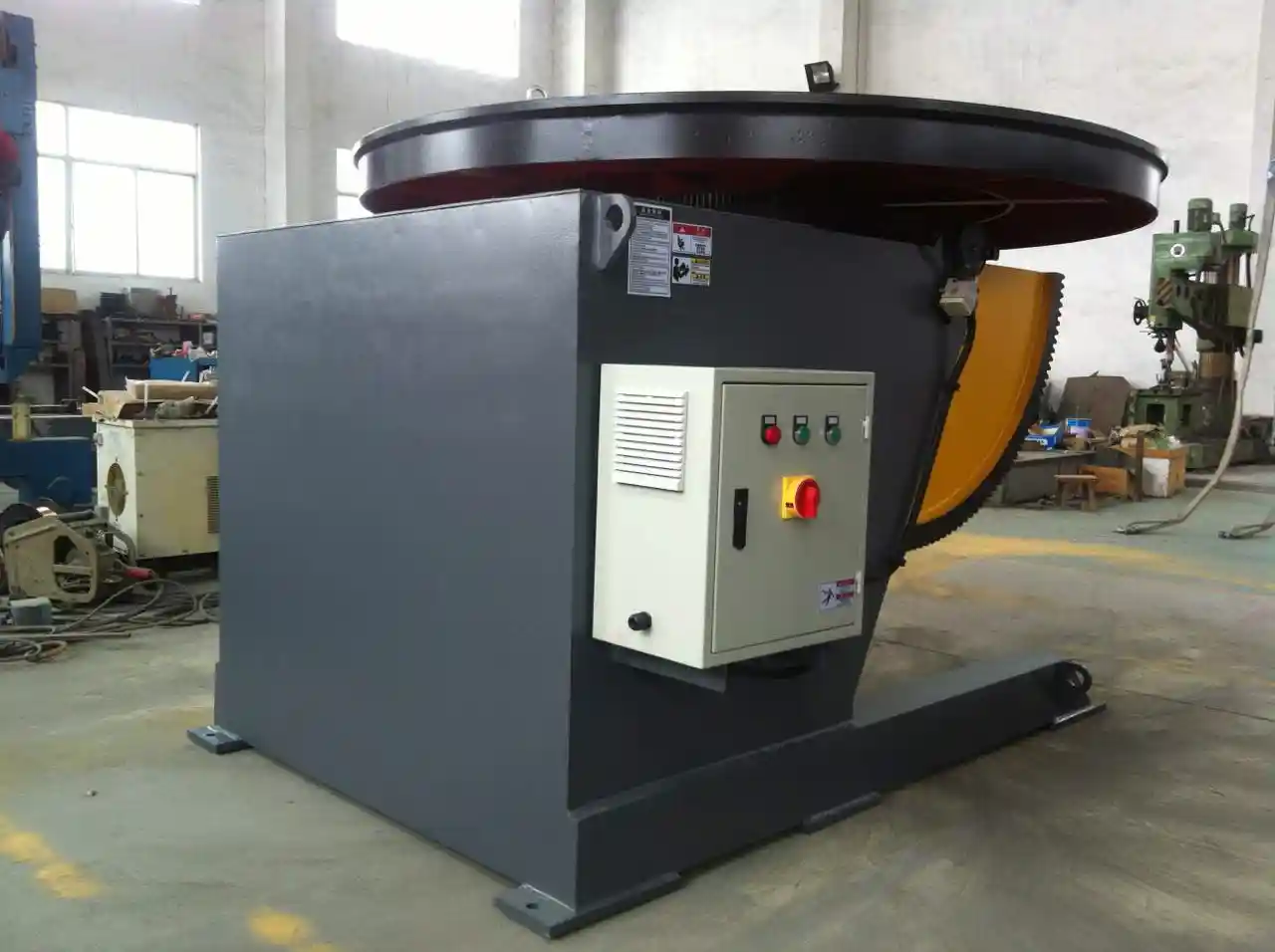
Table size is often reduced to a single question: “what’s the biggest plate you cut?” But the decision also determines material handling layout, loading method, and whether you can support multiple cutting heads. The most common CNC cutting table configurations we supply cover working areas of 1500 mm × 3000 mm, 2000 mm × 4000 mm, 2500 mm × 6000 mm, and 3000 mm × 12000 mm, with custom lengths available. For a fabrication shop processing standard 1.5 m × 3 m plates from the steel supplier, a 2 m × 4 m table gives enough margin for clamping and edge trimming without wasting floor space. Operations cutting long beams or wind tower sections regularly move to 2.5 m to 3 m wide tables and lengths from 8 m to 14 m, often with dual-drive synchronization to maintain ±0.5 mm positioning accuracy over the full travel.
A less obvious factor is plate loading direction. Side-loading tables need extra width for fork clearance; end-loading requires floor tracks or roller conveyors. If you plan to run plasma and flame torches on the same gantry, we design the table with a water tray sized for underwater plasma cutting, which adds about 200 mm to the table width for the tank walls. The table frame itself is a welded steel structure stress-relieved after fabrication; on machines with a cut width beyond 2.5 m, we add a separate rail foundation and independent leg leveling points to prevent twist from thermal expansion.
Torch Configurations: Multi-Torch and Bevel Cutting Options
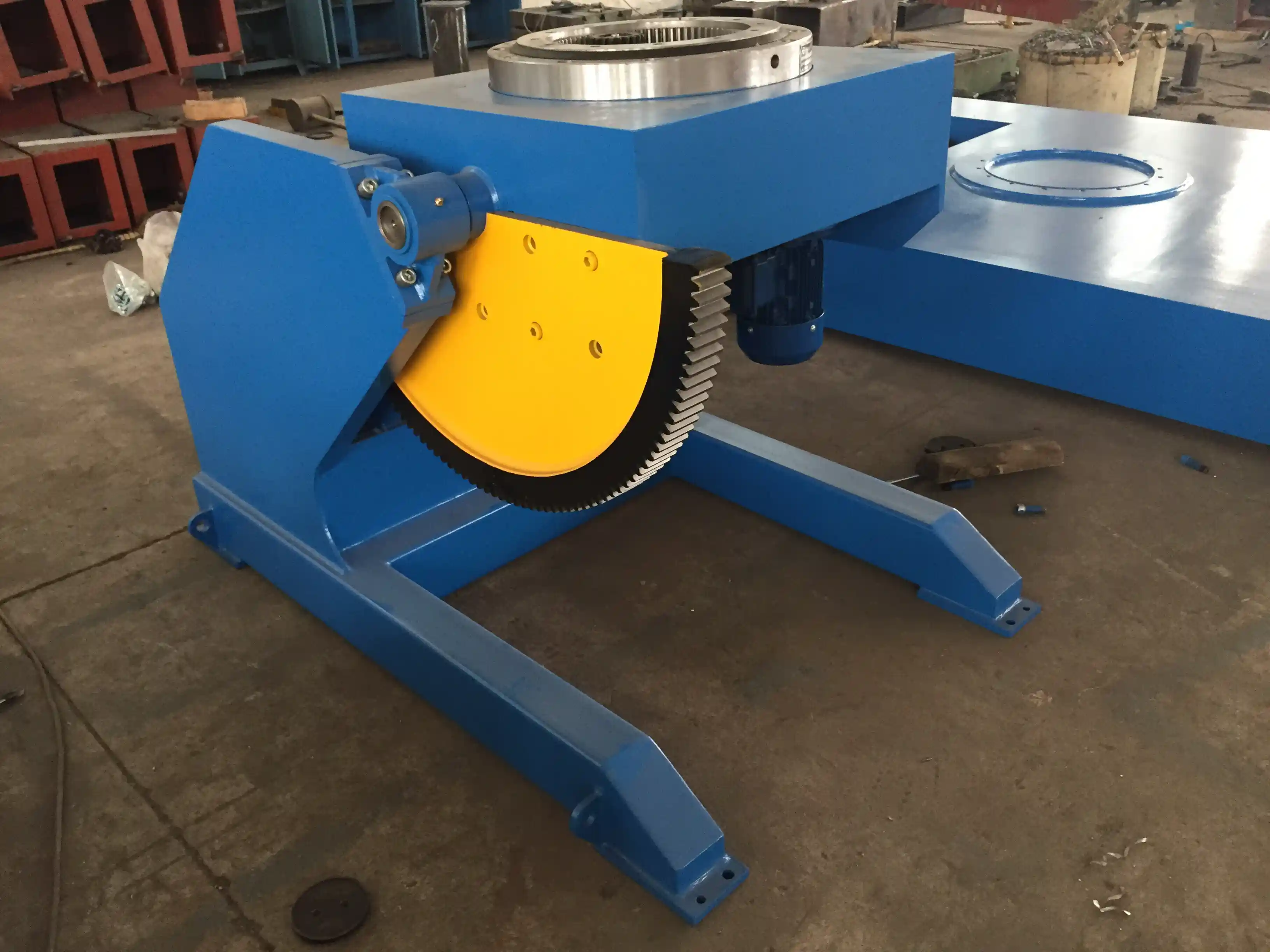
A single plasma torch can handle most cutting jobs, but adding a second or third torch changes productivity dramatically for parts with high piece counts. A dual-torch setup on a 2.5 m table can cut two identical parts simultaneously by splitting the gantry motion; a triple-torch arrangement lets you cut three parts from the same nested sheet. The control system must support independent torch height sensing for each station, otherwise arc voltage variations from plate waviness will cause one torch to drag while the others float. We typically specify a capacitor or laser height sensor per torch and sync them through the CNC controller.
If your parts need weld preparation, an oxy-fuel bevel head mounted beside the plasma torch eliminates a separate machining step. Bevel angle is programmable in most controllers up to 45°, but the actual cut quality depends on the torch carriage rigidity and the kerf compensation algorithm. For shops cutting structural steel, we often combine a 260 A or 400 A plasma unit for straight cuts with two flame torches on a separate carriage, all running on the same rail. The plasma torch handles the thinner web plates at high speed; the flame torches cut the thicker flanges simultaneously. This kind of mixed-torch setup requires a CNC system that can manage multi-process offsets and separate pierce height parameters in real time.
| Torch Configuration | Exemple d'application | Cutting Speed Advantage |
|---|---|---|
| Single plasma (200 A) | General job shop, small batch | Base de référence |
| Dual plasma (200 A each) | High-volume part duplication | Up to 90% cycle time reduction on mirrored parts |
| Plasma + bevel head | Structural weld prep, beveled edges | Eliminates secondary machining |
| Plasma + dual flame | Mixed thickness plate (thin web, thick flange) | Simultaneous multi-process cutting |
| Quad plasma | Multiple identical parts from one sheet | Maximum throughput for nested nests |
Selecting CNC Control Software and Nesting Systems
The physical machine does what the control system tells it to do, and that control system is defined by three layers: the motion controller, the operator interface, and the nesting software. Most CNC cutting machines today run on either an integrated industrial PC with a real-time motion board or a standalone CNC unit with its own processor. For heavy steel fabrication, we lean toward dedicated CNC controllers with an embedded G-code interpreter and a touchscreen interface; they handle environmental noise better and isolate the motion kernel from the operating system.
Nesting software is where daily operating cost is won or lost. A good nesting engine can reduce plate waste by 8–15% compared to manual part placement, and the gap between a basic rectangular nesting algorithm and a true shape-nesting engine with part rotation and common-line cutting shows up in the scrap bin. I’ve seen shops with high-mix production recover the cost of a more capable nesting license within six months on material savings alone. The software must also generate the correct kerf compensation for each torch type, manage lead-in and lead-out paths, and skip pierce points on shared cut lines. When you are specifying a custom machine, confirm that the selected CNC system supports the file formats your design team uses (typically DXF or DWG) and that the post processor can output torch-specific codes for multi-torch setups.
If your operation runs multiple shifts and diverse part families, consider a network-capable system that allows the engineering office to send nests directly to the machine queue. This eliminates USB stick runs and the errors they introduce. We configure the operator station with remote monitoring so that one supervisor can track machine utilization, consumable life, and idle time across shifts.
Supplier Communication: How to Define Your Machine Requirements
The best machine configuration is the one that reflects your real production data, not a checklist. Before you send a specification to a manufacturer, pull your last three months of cutting reports and identify the three part types that consume the most machine hours. Group them by thickness, material grade, and piece count per nest. This data tells us whether you need high-speed plasma for thin gauge, an HD plasma for tighter tolerances, or a laser head for intricate contours. Without it, we default to a median configuration that may be safe but suboptimal.
When you approach a manufacturer, provide the following: maximum and typical plate dimensions, material grades (carbon steel, stainless, aluminum), thickness range, expected monthly output in linear meters or sheets, and any special edge quality or bevel requirements. We also need to know your facility’s power capacity and compressed air system, because a 400 A plasma system with a 5-axis bevel head will draw more and require clean, dry air. Floor loading and crane access affect the table height and gantry clearance.
A common communication gap is the assumption that “custom” means “expensive.” In practice, a well-specified customization aligns the machine with your throughput and may cost less than a larger, over-capacity standard model that forces you to pay for rails and motors you don’t need. If your daily output is 50 plates of 2 m × 6 m, you don’t need an 18 m table—but you might need a second torch. A focused requirement list helps the manufacturer propose exactly what your shop needs.
Avoiding Specification Mistakes That Lead to Performance Gaps
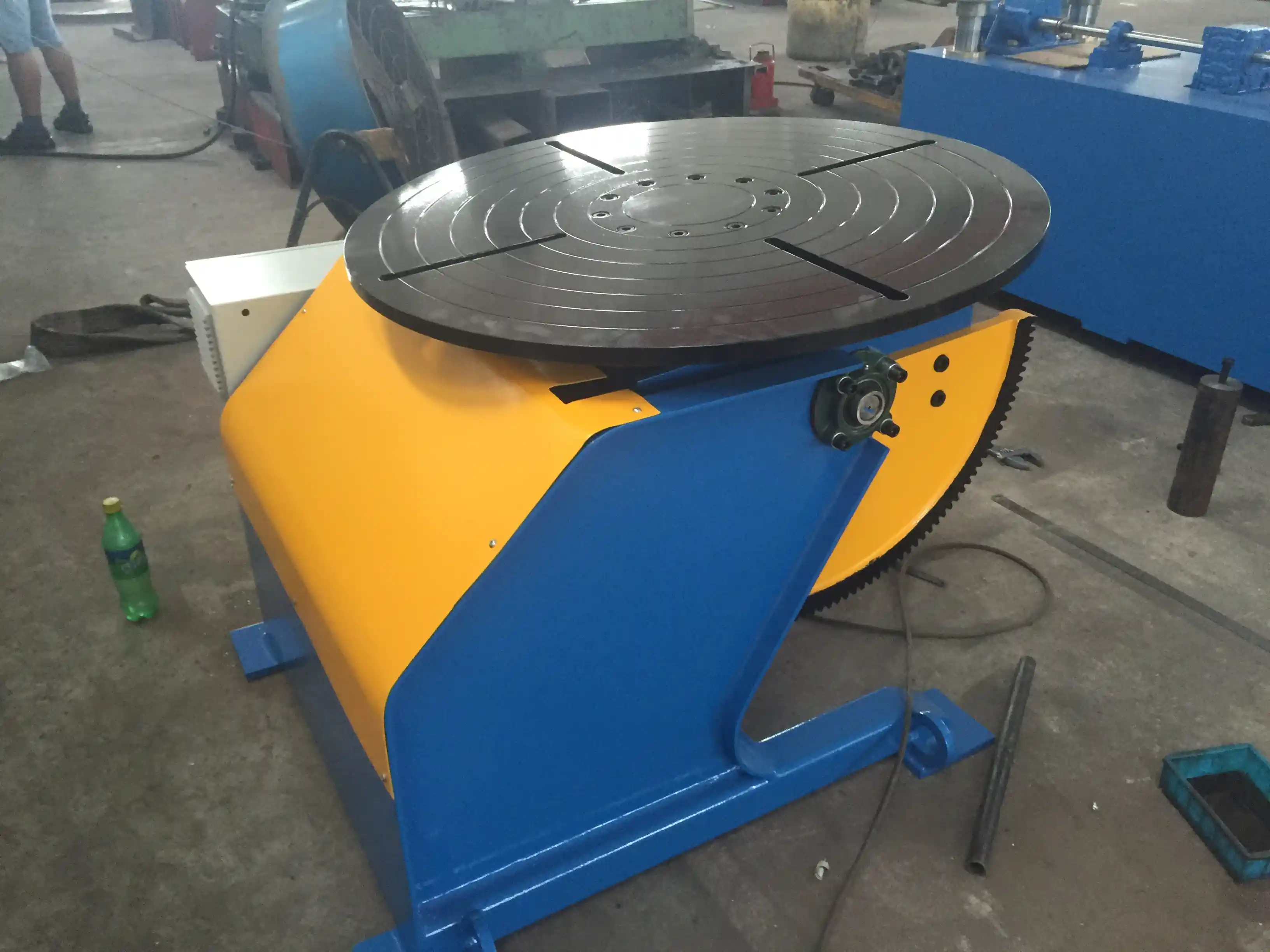
One persistent mistake is undersizing the table for the true working area. A machine rated for 2 m × 6 m effective cut may have a total table footprint that includes lead-in zones, torch parking, and the water tank rim. If you plan to load full-size plates and cut parts right to the edge, you need at least 100 mm of extra travel in both axes. Another common error is specifying a multi-torch setup without verifying that the CNC can maintain independent torch height control during rapid traversal. Without that, one torch collision can damage all the consumables on the gantry.
Software integration oversights also cause problems. If your design team works in SOLIDWORKS or Tekla, confirm that the nesting software can import the part attributes directly and that the post processor respects layer assignments for different torch parameters. I’ve had cases where a shop upgraded to a new plasma source with a different kerf width but failed to update the nesting database, resulting in parts that were consistently undersized by 0.8 mm. A single calibration run with scrap plate and a caliper check would have caught it. Before you accept the machine, request a test cut of your most complex nested layout on your own material grade.
Common Questions When Specifying a CNC Cutting Machine
How do I decide between a single large table and two smaller machines?
If your cutting volume exceeds 1,200 linear meters per shift across widely different thickness ranges, two specialized machines often yield better utilization than one oversized gantry. A dedicated thin-gauge plasma or laser machine runs high acceleration cycles, while a separate heavy-plate flame cutting table runs at slower speeds. Partitioning the load also provides redundancy when one machine is down for maintenance, which matters in tight fabrication schedules.
What software packages work best for multi-torch bevel cutting?
The software must calculate the correct torch angle and offset for each bevel pass, not just apply a global kerf value. Packages like SigmaNEST and Lantek include bevel-specific post processors that handle X, Y, Z, and A/B axis commands simultaneously. In our experience, the more critical factor is the motion controller’s ability to execute the bevel paths smoothly, so confirm that the CNC manufacturer has tested the specific bevel head model with their controller before spec’ing it into your machine.
Is a third-party nesting engine better than the CNC manufacturer’s own software?
It depends on your part variability. For standard rectangular parts with a few hundred nest variations, the basic nesting module inside many machine controllers is sufficient. For complex contours, common-line cutting, and automatic remnant sheet management, a specialized nesting engine reduces scrap and programming time noticeably. I recommend starting with the manufacturer’s included nesting and upgrading only if your scrap tracking shows a clear business case.
Can I upgrade the table length or add a bevel head later?
Mechanically, the rail system must be designed for future extension from the start because the gantry’s linear drive and rack gear sections are matched to the rail length. Adding length later means replacing the rails, rack, and cable drag chain—essentially rebuilding the machine. Adding a bevel head to a machine that wasn’t originally built with the mounting bracket, cable routing, and controller axis reserve is also costly. If you anticipate growth, specify the end-state machine configuration and install only the torches you need today, but ensure the rails, drives, and controller axes are sized for the future load.
What information does the manufacturer need to provide an accurate proposal?
A clear inquiry includes: material types and thickness range, maximum plate dimensions, daily or shift output target in plates or linear meters, whether you need bevel cuts, the design software you use, and your facility’s available power and compressed air. Send these details along with a typical nest file to jay@weldc.com or call +86-510-83555592 with your production goals. A specific data set lets us propose a machine configuration that matches your throughput and floor layout, rather than a generic specification sheet.
Si cela vous intéresse, consultez ces articles connexes :
Des soudures parfaites sur des tubes de grand diamètre grâce à un équipement de laminage professionnel
Une valeur ajoutée exceptionnelle : comment les positionneurs de soudage à hauteur fixe favorisent les avancées dans les secteurs de la construction navale et offshore (2e partie)
Manipulateurs de soudage pour la fabrication de tours éoliennes : Révolutionner l'efficacité de la production
 English
  Español
  Français
  Deutsch
  Português
  Русский